


Link 2000 Remote Control Panel
975-0251-01-01 3–7
* Default setting.
** Refer to voltages under “Battery Charger Voltage Settings”.
Remote Control Wiring
The remote control panel is supplied with 7.62 m or 15.24 m of RJ11 remote
cable. The cable supplied may have 6 conductors; however, only 4 conductors are
required. You may buy standard 4-conductor telephone cable and run up to
15.24 m if desired. Use only a single length of telephone wire—do not splice.
Remote Power Consumption
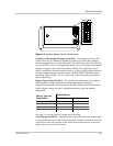
Link 2000 Remote Control Panel
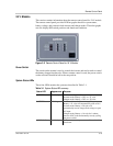
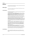
The Link 2000 and 2000R offer increased monitoring and control options. In
addition to providing inverter/charger control, the Link 2000 enables precision
monitoring of DC voltage, current, and amp hours for two battery banks.
The Link 2000R adds the ability to control an engine driven alternator. This
precision regulator transforms an alternator into a 3 stage battery charging system
like the charger in the Freedom 10.
If a Link 2000 or 2000R remote is being used to control the inverter/charger, refer
to the Link manual for setup and control information.
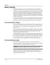
Off Enable: Charger on when
AC connected.*
Idle Sensitivity
56
On On Idle disabled
Off On 15 watts
On Off 6 watts
Off Off 4 watts*
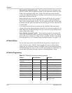
Power Sharing
78
On On 2 amps
Off On 5 amps
On Off 10 amps
Off Off 15 amps*
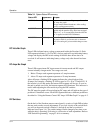
Table 3-2
DIP switch function and position summary
Feature Switch Number Set Point
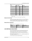
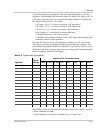
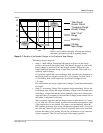
Table 3-3
System current consumption versus idle mode
Idle Mode With Remote Without Remote
Normal Idle 181 mA 120 mA
Idle Circuit Disabled 496 mA n/a
Unit Shut Off 16 mA 7 mA