Avaya M770 ATM Switch User’s Guide 101
Chapter 8
Permanent Virtual Connections (PVCs and PVPs)
This chapter describes how to use the command-line interface to manage PVC
connections in an Avaya M770 ATM Switch. For information about how to access
and use the Avaya M770 ATM Switch command-line interface, see Chapter 3, “How
to Use the Command-line Interface”.
Managing Permanent Virtual Connections (PVCs and PVPs)
Managing PVC connections
Not all ATM equipment currently supports UNI signalling. Therefore, you may
need to manually establish a virtual circuit to make a connection between two ATM
endpoints over an ATM network. These connections are referred to as Permanent
Virtual Circuits (PVCs).
A PVC is a concatenation of Virtual Circuit Links (VCLs), where each VCL is bi-
directional.
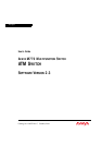
Figure 8.1 illustrates the terms VCL and PVC.
Figure 8.1 A breakdown of a PVC connection
Figure 8.1 shows a PVC, consisting of two VCLs that span three switches. A VCL is
a bi-directional link between two entities, such as two switches or a switch and an
end-station. With respect to switch 2, VCL A is identified by specifying the physical
port (port B) and the VPI/VCI used at that port. Similarly, with respect to switch 1,
VCL A is identified by specifying the physical port (port A) and the VPI/VCI used
at that port. Note that the VPI/VCI in the same switch, is the same at both ports. The
PVC connection could be between 2 ports on the same module or between 2
modules on the same switch (through the backplane). This means that port B and
port C can be on one module or on 2 different modules on the same switch.
Switch 1 Switch 2 Switch 3
Port A
Transmit Receive
Receive
Receive Transmit
Transmit
Port B
Port C
Port D
PVC connection
VCL A
VCL B