


18 Installation
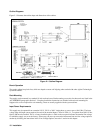
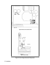
Outline Diagrams
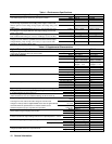
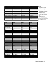
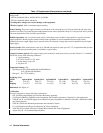
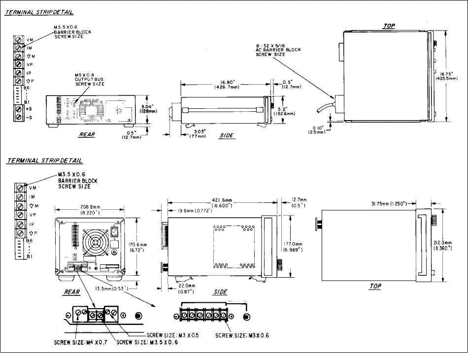
Figure 2-1 illustrates the outline shape and dimensions of the cabinet.
6023A ONLY
6028A
ONLY
Figure 2-1. Outline Diagram
Bench Operation
The supply cabinet has plastic feet, which are shaped to ensure self-aligning when stacked with other Agilent Technologies
System II cabinets.
Rack Mounting
The supply can be mounted in a standard 19-inch rack enclosure. Rack mounting accessories for these units are listed in the
ACCESSORIES paragraph in Section I. Complete installation instructions are included with each rack mounting kit.
Support rails are also required for rack mounting. These are usually supplied with the system cabinet.
Input Power Requirements
This supply may be operated from a nominal 120 V, 220 V or 240 V single-phase ac power source (48-63 Hz). The input
voltage range and input current required for each of the nominal inputs is listed in Table 1-1. To operate from 100 Vac line,
Option 100 must be installed. This is a factory-installed option. A label on the rear panel indicates the nominal line voltage
for which the supply was set at the factory. If necessary, the user can convert the instrument from one line voltage option to
another by following the instructions in the “Line Voltage Option Conversion” section in this chapter.