


Installation 19
Power Connection
Caution: Connection of this supply to an ac power source should only be performed by an electrician or other
qualified person. Before connecting the supply to the ac power source, check the label on the rear panel to
ensure that the supply is set for the correct ac voltage to be used. If necessary, convert the line voltage to
another by following the instructions under “Line Voltage Conversion”.
Agilent Models 6010A, 6011A, 6012B and 6015A.
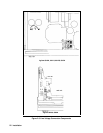
To connect input power, to the instrument proceed as follows:
a. Remove the AC filter assembly cover by unscrewing the four locating screws.
b. Insert the power cord through the strain relief clamp located on the cover.
c. Connect the wires to the terminal block in accordance with the prevailing color codes.
Green or green/yellow to the terminal labeled "
''
White or blue wire to the terminal labeled "N'' *
Black or brown wire to the terminal labeled ''L"
* In a 2-phase system, such as 208 in the USA, the second phase is connected to the "N'' terminal.
WARNING: For proper protection by the instrument circuit breaker, the wire connected to the "L’’ terminal on
the instrument must be connected to the "L’’ side of the line (hot); the wire connected to the ’’N"
terminal must be connected to the "N" side of the line (neutral or common).
To protect operating personnel, the wire connected to the "
’’ terminal must be connected to
earth ground. In no event shall this instrument be operated without adequate ground connection.
d. Replace the cover, tighten all four screws and tighten the strain relief clamp. (All four screws must be tightened for unit
to meet RFI specifications.)
e. Connect the other end of the power cord to an appropriate power source.
Note: Connections to the ac power line must be made in accordance with applicable electrical codes. The
international color code for identifying mains supply conductors is green/yellow, blue, and brown for
earth, neutral, and line respectively. Corresponding USA/Canadian codes are green, white, and black.
Caution: Before applying power to the instrument, check to see that the rear-panel circuit breaker CB1 is on. The
breaker may trip due to rough handling during transit. If the breaker is found to be tripped at any other
time for unknown reasons, refer to the troubleshooting procedures in the Service Manual.
Agilent Models 6023A and 6028A.
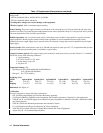
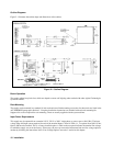
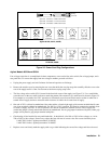
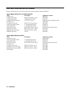
The power supply is shipped from the factory with a power-cord plug appropriate for the user’s location. Figure 2-2
illustrates the standard configuration of power-cord plugs used by Agilent Technologies. With each drawing is the Agilent
Part Number for a replacement power cord equipped with a plug of that configuration. If a different power cord is required,
contact the nearest Agilent Technologies Sales and Service office.
To protect operating personnel, the National Electrical Manufacturers Association (NEMA) recommends that the instrument
panel and cabinet be grounded. This supply is equipped with a three-conductor power cable; the third conductor is the
ground conductor. When the cable is plugged into an appropriate receptacle the supply is grounded. In no event shall this
supply be operated without an adequate cabinet ground connection.