


28 Operating Instructions
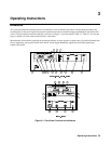
Initial Setup and Interconnections
WARNING: Turn off input ac power before changing any rear-panel connection and make certain all wires
and straps are properly connected and terminal block screws are securely tightened before
reapplying power. Be certain to replace both terminal block covers before reapplying power to
avoid exposing the operator to hazardous voltages.
Connecting the Load
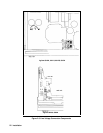
Load connections to the power supply are made at the + and – output terminals on the rear panel. Higher power units have
output bus bars. The bus bars are covered by an impact-resistant plastic cover, which is secured to the unit with four M4 x 8
screws. Be certain to replace the cover after making connections. Two factors must be considered when selecting wire size
for load connections, conductor temperature and voltage drop.
To satisfy safety requirements, the wires to the load should be at least heavy enough not to overheat while carrying the
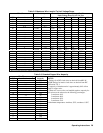
maximum power supply output current that would flow if the load were shorted. Use Tables 3-2 and 3-3 to determine the
proper wire gauge for load connections to the power supply. When 2 or more wires are bundled together, the current
carrying capacity of each wire is reduced (see Table 3-3, Note 3). All wires must be properly terminated with connectors
securely attached. Do not connect unterminated wires to the power supply. Wire sizes of AWG #14 (2,5mm
2
) or smaller are
normally used only for sense leads.
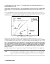
The minimum wire size required to prevent overheating will not usually be large enough to provide good voltage regulation
at the load. For proper regulation the load wires should be large enough to limit the voltage drop to no more than 0.5 volts
per lead. Table 3-2 lists resistivity for various wire sizes and the maximum lengths that may be used to limit voltage drop to
0.5 volts for various currents. Lengths listed are the sum of the lengths of the (+ ) and ( - ) load wires. Lengths are given in
meters and (feet).
To determine maximum lengths (in meters or feet) for currents not listed, use the formula:
resistancecurrent x
1000 x 0.5
=length maximum
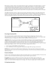
where current is expressed in amps and resistance is expressed in ohms/km or ohms/1000 feet. If load regulation is critical,
use remote voltage sensing .
WARNING: While calculating load wire size, remember that the wire must be large enough not to overheat
while carrying the current that would flow if the load were shorted.
Table 3-3 lists the maximum current-carrying capacity (ampacity) for various sizes of stranded copper wire.
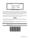
If multiple loads are connected to one supply, each load should be connected to the supply's output terminals using separate
pairs of connecting wires. This minimizes mutual coupling effects and takes full advantage of the supply's low output
impedance. Each pair of connecting wires should be as short as possible and twisted or shielded to reduce noise pickup and
radiation.
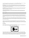
If load considerations require the use of output distribution terminals that are located remotely from the supply, then the
power supply output terminals should be connected to the remote distribution terminals by a pair of twisted or shielded
wires. Each load should be separately connected to the remote distribution terminals. Remote voltage sensing is suggested
under these circumstances. Sense either at the remote distribution terminals, or (if one load is more sensitive than the
others) directly at the most critical load.