


Operating Instructions 27
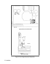
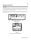
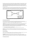
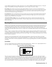
a. Check that the rear-panel mode switches are set as shown in Figure 3-3.
b. Check that + lead is connected to +S and the – lead is connected to –S and tightened securely. The + Sense lead is
connected to + Output and the
−
sense lead is connected to
−
Output lead at the factory.
c. Check that the rear panel label indicates that the unit is set for the mains input voltage to be used. If not, refer to “Line
Voltage Conversion” in chapter 2.
d. Plug the unit into the appropriate ac power outlet.
e. Turn the Voltage control all the way down (fully counter clockwise) and the Current control up slightly clockwise to
ensure CV operation.
f. Check that the recessed OVP ADJUST control on the front panel is fully clockwise.
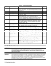
g. Press the top of the LINE rocker switch in to turn the power supply on. You should hear the fan. Check that the CV
indicator remains on.
h. The VOLTS and AMPS displays should indicate approximately 0.00.
i. Press the momentary-contact DISPLAY OVP pushbutton switch and check that VOLTS display indicates maximum
OVP for the power supply.
j. Press the DISPLAY SETTINGS switch, Turn the CURRENT knob clockwise, and check that the AMP setting
increases. The CV indicator should be on and the CC indicator should be off.
k. Turn the VOLTAGE control clockwise and check that the output voltage increases from zero to full output voltage as
indicated on VOLTS display. Continued clockwise rotation may cause VOLTS display to indicate + OL.
l. Check the overvoltage protection circuit by turning OVP ADJUST control counterclockwise until OVP circuit trips.
Output should drop to 0 V, CV indicator turns off and OV indicator turn on .
m. Reset the OVP circuits by turning OVP ADJUST control fully clockwise and turning unit off and back on.
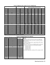
n. To check the constant current circuit, turn the power supply off and short rear panel + and - output terminals with a wire
of sufficient gauge to carry the supply's maximum current output (see Table 3-3).
o. Turn the power supply on and adjust the CURRENT control clockwise. Check that the output current increases from
zero to full output current as indicated on AMPS display. Continued clockwise rotation may cause AMPS display to
indicate + OL. The CC indicator should be on and CV indicator should be off.
p. Turn off the power supply, remove the short from the output, and read following instructions before connecting load to
supply.