


Operating Instructions 39
Constant Current Output, Voltage Control.
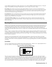
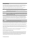
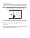
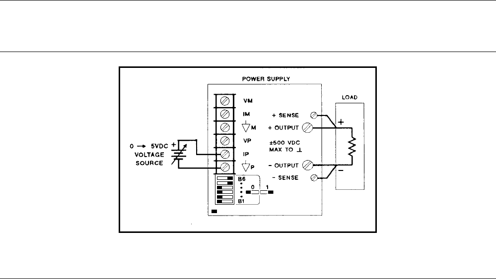
The setup shown in Figure 3-11 allows the output current to be varied by using an external voltage to program the supply. A
voltage source variable from 0 to + 5 volts produces a proportional output current from zero to full scale. The static load on
the programming voltage source is less than 5
µ
A. A source resistance of less than 10k is necessary to avoid degradation of
offset and drift specifications.
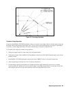
Note: If external resistors are used to limit the remote-programming voltage to 5Vdc, the resulting high
programming-source resistance can degrade the power supply’s programming speed, offset and drift
performance. Limit the equivalent source resistance to 10k ohm maximum. Figure 3-9 shows a convenient
way to calculate suitable voltage-divider resistance values for a 5k ohm source resistance.
Figure 3-11. Voltage Programming of Output Current
Multiple-Supply Operation
The power supply can be operated in combination with other power supplies to provide increased output capability. Auto-
parallel operation of two power supplies can provide up to twice the output current. Other configurations are possible.
Contact Agilent Technologies, Power Products Division for specific application assistance.
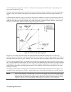
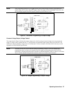
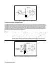
Auto-Parallel Operation
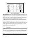
Two units can be connected in an auto-parallel combination to provide twice the output current capability. One of the power
supplies, the master, is programmed normally. The other power supply, the slave, is analog programmed by the master. The
mode switches of the slave must be set so that the slave is analog programmed by the master. Figure 3-12 shows the rear-
panel mode switch settings and terminal connections for auto-parallel operation.
= Handle