


Operating Instructions 35
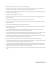
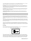
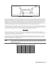
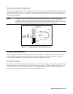
Figure 3-6. Remote Voltage Sensing
Because the sensing leads carry only a few milliamperes, the wires used for sensing can be much lighter than the load leads.
Each sense lead should have no more than 0.2 ohms resistance. Use the resistivity columns in Table 3-2 to determine the
minimum wire size for the length of sense leads being used. The sense leads should be a shielded, twisted pair to minimize
the pickup of external noise. Any noise picked up on the sensing leads will appear at the supply’s output, and CV load
regulation may be adversely affected. The shield should be grounded at the power supply end only, and should not be used
as one of the sensing conductors. The sensing leads should be connected as close to the load as possible.
If slightly degraded CV load regulation can be tolerated, the power supply will provide remote voltage sensing with up to 2
Vdc drop in each load lead and with more than 0.2 ohms resistance in each sense lead. As the voltage drop in the load leads
increases, the load voltage error due to sense-lead resistance increases according to the formula:
(2Rs + 0.5)V1
1000
where Rs is the resistance in ohms of each sense lead and Vl is the voltage drop in each load lead. For example, if the
resistance in each sense lead is 1 ohm and the voltage drop in each load lead is 2 Vdc, the load voltage might differ by [2(1)
+ 0.5] 2/1000 = 5 mVdc from that with no sense-lead.
The sensing leads are part of the supply’s programming circuits, so they should be connected in such a way as to make it
unlikely that they might inadvertently become open circuited. If the sense leads open during operation, the voltage at the
load will rise slightly above its’ programmed value.
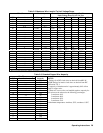
Note: The power supply includes protection resistors that reduce the effect of open sense leads during remote-
sensing operation. If a sense lead opens there will be a change in the output voltage. See Table 3-4 for the
approximate voltage change.
Table 3-4. Voltage change due to open sense lead
Model +S -S Both
6010A 1.6% -0.1% 1.5%
6011A 4% 1% 4.8%
6012B 1.6% -0.1% 1.5%
6015A 1.6% -0.1% 1.5%
6023A 4% 1% 4.8%
6028A 4% 1% 4.8%