


Operating Instructions 29
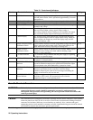
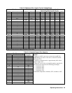
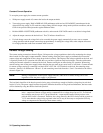
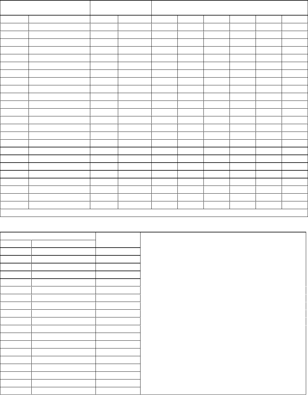
Table 3-2. Maximum Wire Lengths To Limit Voltage Drops
Wire Size Resistivity Maximum Length In Meters (Feet)To
Limit Voltage Drop To 0.5V Or Less
AWG Cross-section (mm
2
)
Ω/kft Ω/km
5 A 10A 17 A 30A 50A 120A
22 16.15 (6.19)*****
0,5 40.12.5*****
20 10.16 (9.8)*****
0,75 26.73.71.8****
18 6.388 (15.6)(7.8)****
1 20,05.02.5****
16 4.018 (24.8) (12.4) (7.3) * * *
1,5 13.77.33.64****
14 2.526 (40) (19.7) (11.6) (6.6) * *
2,5 8.21 12.2 6.1 3.5 * * *
12 1.589 (62.9) 13.46) (18.5) (10.49) * *
4 5.09 19.6 9.8 5.7 3.27 * *
10 .9994 (100) (50) (29.4) (16.68) (10.01) *
6 3.39 29.5 14,7 8.6 5.9 * *
8 0.6285 (160) (79.5) (46.7) (26.52) (15.91) *
10 1.95 51,2 25,6 15 8.55 5.13 *
6 0.3953 (252) (126.5) (74.4) (42.16) (25.3) *
16 1.24 80.6 40,3 23.7 13.44 8.06 *
4 0.2486 (402) (201) (118) (67.04) (40.23) (16.76)
25 0.795 125.7 62.8 37 20.96 12.58 5.24
2 0.1564 (639) (319) (188) (106.5) (63.94) (26.64)
35 0.565 176.9 88.5 52 29.5 17.7 7.37
50 0.393 254.4 127 74.8 42.4 25.45 10.6
0 0.09832 (1017) (508) (299) (169.5) (101.7) (42.38)
* Wire not rated for power supply maximum current rating.
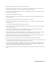
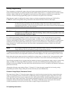
Table 3-3. Stranded Copper Wire Ampacity
Wire Size
AWG Cross Section (mm
2
) Ampacity NOTES:
22 5.0
20 8.33
0.75 10
1 13.5
18 15.4
1.5 16
16 19.4
2.5 25
14 31.2
432
12 40
640
10 55
10 63
875
6 100
4 135
2 180
0 245
1. Ratings for AWG-sized wires are derived from MIL-W-
5088B. Ratings for metric-sized wires are derived from IEC
Publication 335-1.
2. Ampacity of aluminum wire is approximately 84% of that
listed for copper wire.
3. When two or more wires are bundled together, ampacity for
each wire must be reduced to the following percentages:
2 conductors 94%
3 conductors 89%
4 conductors 83%
5 conductors 76%
4. Maximum temperatures: Ambient, 50°C; conductor, 105°C