132 Current Loop Compensation (Series 668xA Only)
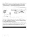
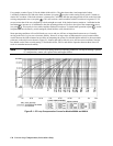
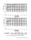
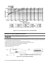
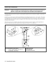
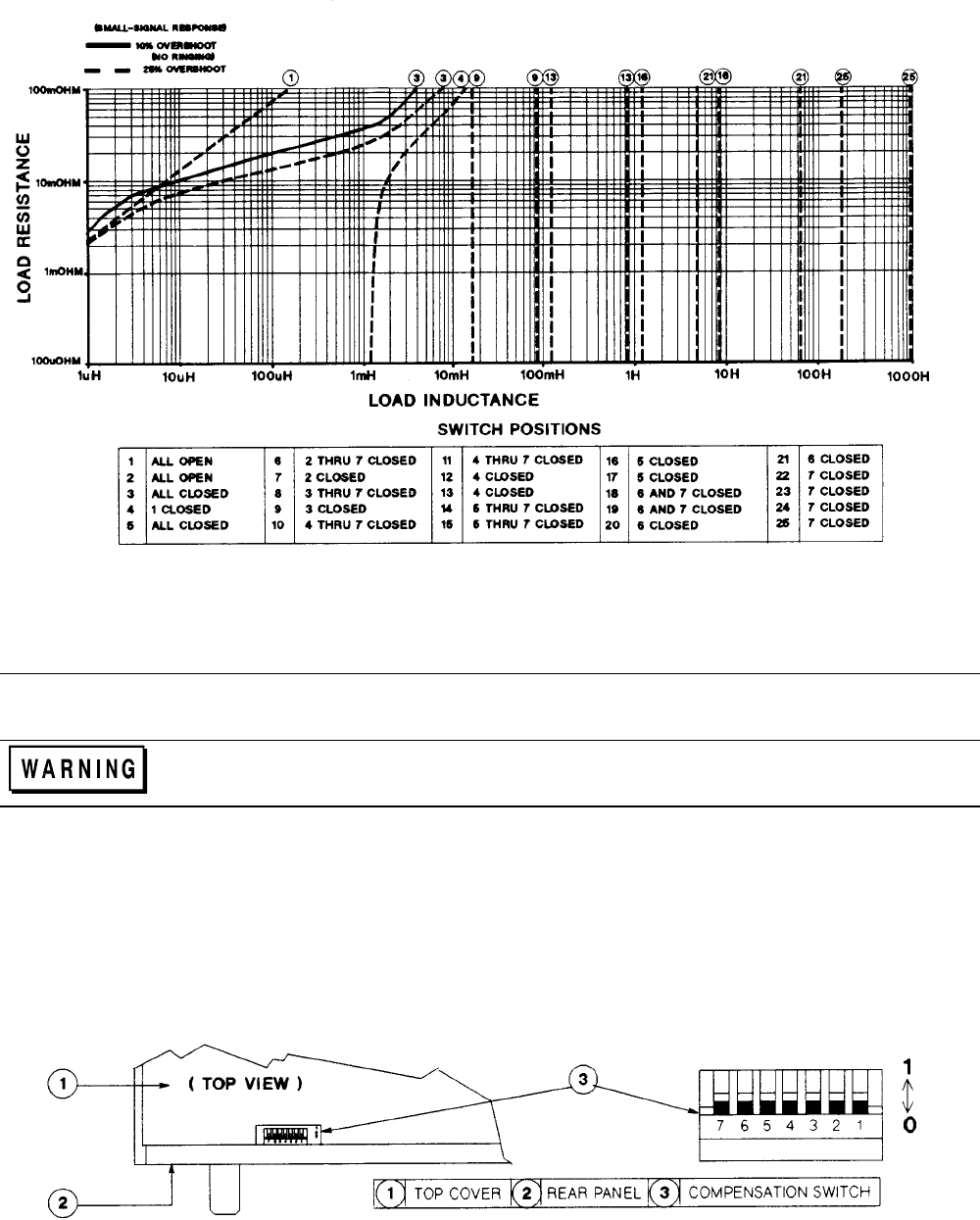
Figure E-1. CC Loop Compensation Curves For Model 6684A
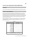
Setting the Loop Compensation Switch
SHOCK/ENERGY HAZARD. This procedure involves removing the outside cover and should only
be done by qualified electronics service personnel.
1. Turn off the power switch and disconnect the power cord from the power source. If this is not possible, remove the three
line fuses from the rear panel (see Figure 2-4).
2. Remove the four screws that secure the two carrying straps and outside cover.
3. Spread the bottom rear of the cover and pull it back to disengage it from the front panel.
4. Remove the cover by sliding it back towards the rear of the supply.
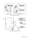
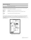
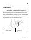
5. Locate the compensation switch (see Figure E-2).
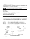
6. Move the switches to the desired position.
7. Replace the outside cover.
Figure E-2. CC Loop Compensation Switch


