User Connections 69
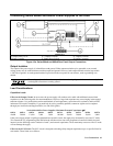
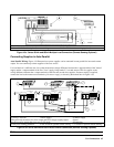
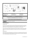
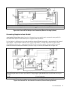
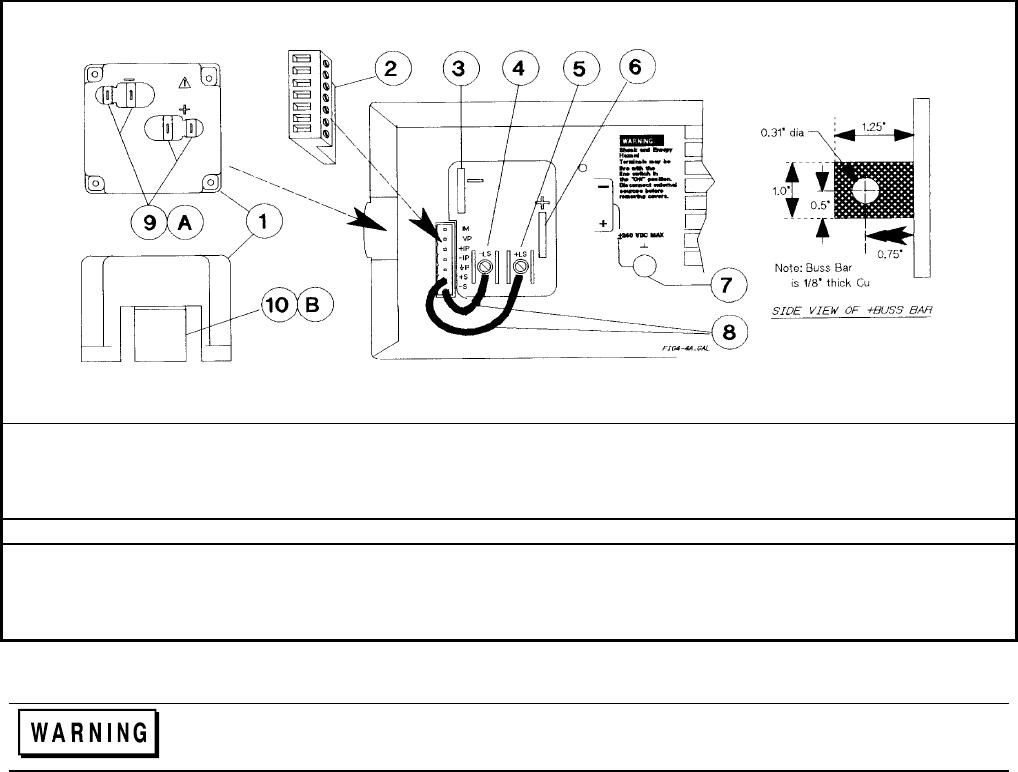
Output Safety Cover Analog Connector -Output Bus Bar
-Local Sense Terminal + Local Sense Terminal + Output Bus Bar
Signal Common Local Sense Jumpers Rear Knockouts
Bottom Knockout
A Insert screwdriver blade in slot and pry out B Bend along joint and break off
WARNING
DO NOT LEAVE UNCOVERED HOLES IN OUTPUT COVER. IF TOO MANY
KNOCKOUTS HAVE BEEN REMOVED, INSTALL A NEW COVER.
Figure 4-4a. Series 667xA Rear Panel Output Connections
The earth ground terminal on the rear panel is a low-noise signal ground for convenience only. It is not
designed to function as a safety ground.
Load Considerations
Capacitive Loads
In most cases, the power supply will continue to be stable with additional external load capacitors. However, large load
capacitors may cause ringing in the supply's transient response. It is possible that certain combinations of load capacitance,
equivalent series resistance, and load lead inductance will result in instability. If you need help in solving a stability
problem, contact a service engineer through your local Sales and Support Offices (see end of this guide).
If the power supply output is rapidly programmed into capacitive loads, the supply may momentarily cross into constant
current (CC) mode. This extends the CV programming time and limits the maximum slew rate to the programmed current
divided by the total internal and external capacitance. These momentary crossovers into CC mode will not damage the
supply.
Inductive Loads
Inductive loads provide no loop stability problems in CV mode. However, in CC mode inductive loads will form a parallel
resonance network with the power supply's output capacitor. Generally, this will not affect the stability of the supply, but it
may cause ringing of the current in the load. Ringing will not occur if the Q (quality factor) of the parallel resonant network
is ≤1.0. Use the following formula to determine the Q of your output.


