


-22-
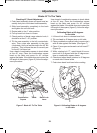
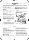
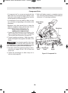
The miter detent override feature allows the detent
action to be locked out, allowing for micro adjust-
ments at any miter angle. When the desired miter
angle is to close to a standard mitering angle that
has a detent slot, this feature prevents the wedge
on the miter arm from slipping into the detent slot
on the base.
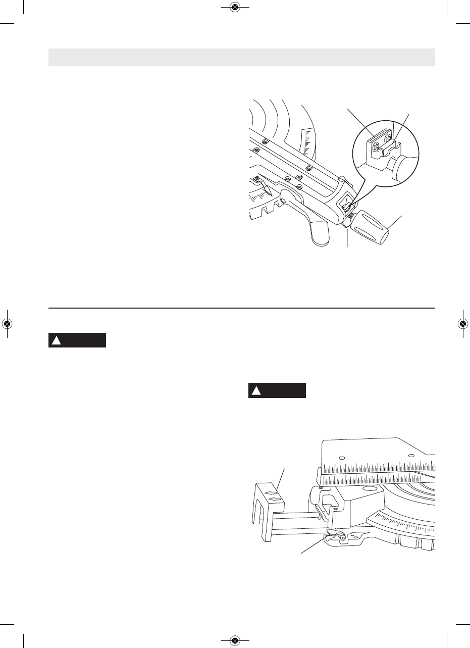
1. Lift and hold the miter detent lever (under base
arm).
2. Push the detent override clip forward and latch
in place over edge. Release miter detent lever
(Figure 24).
3. Move miter arm to any position on the miter
scale.
4. Lock the miter lock knob to retain miter position.
)>8B4=6064
5. Loosen miter lock knob and lift the miter detent
lever to release the detent override clip. The
clip should automatically disengage and the
table should lock into any desired miter detent.
0B82(0F$?4A0C8>=B
"8C4A4C4=C$E4AA834
10
5
0
0
2
12
45
40
50
55
60
4C4=C
$E4AA834;8?
;8?364
"8C4A
4C4=C!4E4A
"8C4A
!>2: =>1
86DA44C4=C$E4AA834
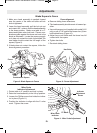
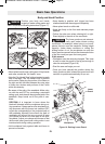
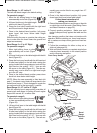
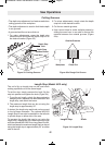
So as to provide sufficient (mini-
mum 6”) spacing from hand to saw
blade, extend the sliding fences and base exten-
sions when making extreme bevel, miter or com-
pound cuts.
The base extensions can also be used to provide
extra support for long workpieces.
(;838=60B4
1. Loosen the base extension clamping levers
(Figure 25).
2. Extend sliding base extensions to the desired po-
sition.
3. Press the levers down to clamp the extensions
into place.
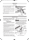
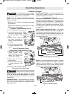
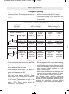
(;838=64=24
1. Loosen the fence locking knobs (behind fence).
2. Slide fence to proper position.
3. Tighten knobs to lock fence into place.
)>)4<?>A0A8;H'4<>E4(;838=64=24
Some extreme compound angles make it necessary
to remove one of the sliding fences.
1. Unscrew fence knob until at least 1/2” of thread
shows.
2. Slide fence to its centermost position.
3. Lift fence to remove.
4. Tighten knob
After the cut is complete, reinstall the sliding fence.
To reinstall the sliding fence, reverse this procedure.
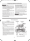
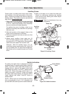
During transportation, sliding base
extensions and fences should al-
ways be secured in the fully closed position.
See page 20 for information about other types of
workpiece support.
(;838=64=24B0=30B4GC4=B8>=B
!
WARNING
(;838=64=24B
0=30B4
GC4=B8>=B
0B4GC4=B8>=B
;0<?8=6;4E4AB
86DA4(;838=64=24B0=30B4GC4=B8>=B
!
CAUTION
2610009642 10/09 E:2610009642 10/09 E 10/20/09 3:18 PM Page 22