


10
Operating Instructions and Parts Manual
Airless Paint Systems
www.chpower.com
Electrical System (Cont.)
REPLACEMENT OF ELECTRICAL
COMPONENTS
NOTE: Refer to Electrical System
Diagram (page 20) and LCD Diagram
(page 22).
PRESSURE CONTROL ASSEMBLY
(ELECTRICAL CONTROL BOARD)
1. Unplug machine's power cord.
2. Remove four screws from pressure
control assembly.
3. Disconnect all leads from pressure
control assembly.
4. Reassemble in reverse order.
SENSOR
1. Remove the screws and lower the
pressure control assembly.
2. Disconnect swivel from sensor by
holding sensor with 7/8" wrench
and loosening swivel with 11/16"
wrench.
3. Disconnect sensor lead from the
board. Carefully pull sensor lead
out of the terminal box and remove
sensor.
4. Reassemble in reverse order.
POTENTIOMETER
1. Lower pressure control assembly as
described above.
2. Disconnect potentiometer lead
from pressure control assembly.
3. Use a 1/16" allen wrench, loosen set
screw in the potentiometer knob
and remove knob and spacer.
4. Using a 1/2" wrench or deep socket,
remove the nut from the
potentiometer shaft assembly.
5. Pull entire potentiometer assembly
out of terminal box.
6. Replace in reverse order.
LIQUID CRYSTAL DISPLAY (LCD)
1. Lower pressure control assembly as
described above.
2. Unscrew the four nuts (6/32") and
remove LCD Display assembly.
3. If unable to loosen the four nuts,
hold them and unscrew the four
screws. Then remove the LCD
Display Assembly. If the display is
removed in this manner, the mylar
label must be replaced.
4. Reassemble in reverse order, while
making sure that the four spacers
and the four washers are in place.
Tighten the four nuts handtight
and seal with blue loctite. DO NOT
overtighten the nuts as this will
damage the display.
ON-OFF TOGGLE SWITCH
1. Lower the pressure control
assembly as described above.
2. Disconnect the two wires on the
switch.
3. Use a 9/16" wrench to loosen the
nut on the toggle switch shaft.
4. Reassemble in reverse order.
FUSE HOLDER
1. Lower pressure control assembly as
described above.
2. Disconnect the two wires on the
holder.
3. Remove holder cover and fuse.
4. Use 11/16" wrench to remove the
nut from the holder shaft.
5. Reassemble in reverse order.
Service
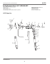
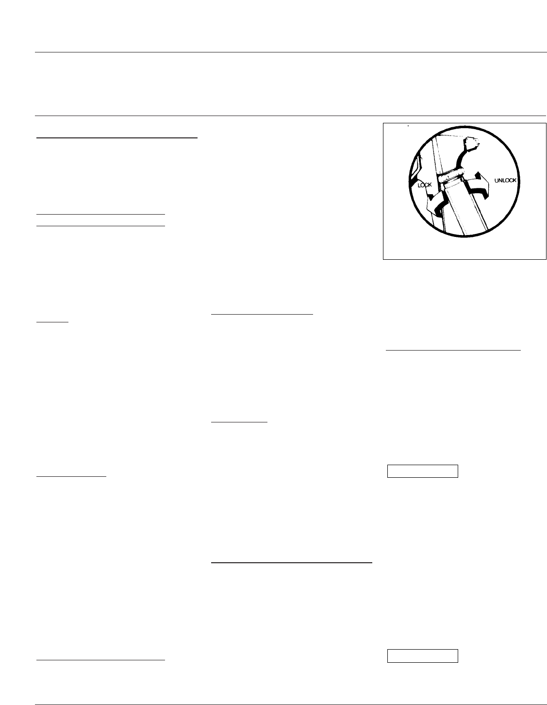
SPRAY GUN
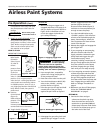
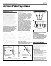
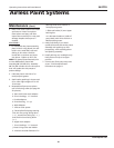
Prior to servicing gun: Attach spray
gun to hose and tighten fittings
securely. Set the gun trigger lock. The
gun trigger lock should always be set
when the gun is not being triggered
(see Figure 10).
Hold gun with trigger locked and push
trigger against the lock . Then adjust
nut so that the retainer will move
freely back and forth approximately
1/32" to allow valve spring unit to seat
the valve ball.
IMPORTANT: Readjust nut periodically
for wear of valve seat and valve ball.
Otherwise, leakage will occur.
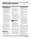
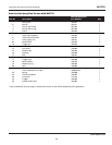
REPLACING VALVE BALL HOLDER
Kit #2-007
Parts Needed: 3 Tip Washers, 1 Valve
Seat, 1 Valve Ball Holder, 2 Seals-Teflon
Dismantling:
1. Unscrew rev guard and remove spray
tip and seal.
2. Unscrew valve seat with 1/2" socket
wrench.
When removing and
replacing valve
seat, hold the trigger in the open
position so that the valve ball is lifted
off the valve seat. Failure to life the
ball off the seat will result in a
scrathed, leaky valve.
3. Unscrew valve ball together with the
brass part of the assembly. Do not pull
on the parts or the packing may get
damaged.
4. Unscrew the valve ball from the
brass part of the assembly.
Reassembling is done in reverse
sequence. Screw the new valve ball
with holder into the brass part.
Tighten valve ball
and brass part on
threaded end of the shaft by hand until
you feel a positive stop. Do not tighten
NOTICE
NOTICE
Figure 10 - Setting Trigger Lock
AL2710