12
Operating Instructions and Parts Manual
Airless Paint Systems
www.chpower.com
Service (Cont.)
Replace worn or damaged parts.
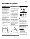
6. If gear grease needs replacing,
replace with gear grease (Part No.
331-132)
7. Clean mating surfaces of cover and
box thoroughly.stick Seal the
mating surfaces with gasket sealer.
8. Reassemble in reverse order.
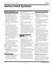
PISTON ROD, UPPER CHECK VALVE
1. Disconnect fluid pump as shown on
page 11.
2. Place piston in block (Tool PN 331-
195) with the 3/8” dowel pin (Tool
PN 331-196).
NOTE: Do NOT use smaller diameter
pin than PN 331-196 to hold piston.
3. Place a 1/4” allen wrench into
bottom of piston. Unscrew retainer
from piston. Clean all parts and
inspect them for wear and damage.
Inspect the surface of piston and
seat for wear or damage.
4. To disassemble the piston assembly,
place in block using dowel pin and
hold in vise. Install ball, seat and O-
ring in this order. Use blue loctite
242 on retainer and screw into
piston. Tighten to 20 ft. lbs.
LOWER SUCTION VALVE
1. Unthread suction nut and remove
suction assembly from pump body.
2. Remove sxuction seat assembly, O-
ring, ball and retainer.
3. Clean all parts and inspect them for
wear or damage, replacing parts as
needed.
4. If lower seat needs replacing, you
can replace the suction seat
assembly (PN 331-292).
5. Clean inside of pump body.
6. If no further pump service is
needed, reassemble the lower
check valve assembly, O-ring, ball
and retainer in the suction nut and
screw nut onto pump body. Tighten
suction nut with rod tool.
Maintenance
REGULAR MAINTENANCE
1. Keep the displacement pump
packing nut/wet cup 1/3 full of TSO
(Throat Seal Oil) at all times. The
TSO helps protect the packings and
rod.
2. Inspect the packing nut daily.
Your pump has a patented Triple
Life Packing System. Packing life
will be extended a minimum of
three times if the following
"Packing Tightening" procedure is
followed:
Inspect packing nut. (Do NOT spray
while inspecting.) If seepage of paint
into the packing nut and/or movement
of the piston upward is found, the
packing nut should be tightened
enough to stop leakage. Do not
overtighten, as this will damage the
packings and reduce the packing life.
ELECTRIC MOTOR MAINTENANCE
1. LUBRICATION:
This motor is supplied
with prelubricated ball bearings,
lubricated for life of bearing.
2. MOTOR BRUSHES:
These need
periodic inspection and replacement
according to wear. Brush wear is
influenced by individual application.
It is recommended that brush wear
be checked at early intervals of
operation. This will help determine
when inspections will be needed in
the future. Standard Leeson brushes
for this motor have an initial length
of 3/4”. When the brushes are worn
to a length of 3/8”, they should be
replaced.
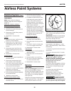
3. CHANGING BRUSHES:
Follow these
instructions:
a. Unplug machine.
b. Open the two covers at the rear
of motor.
c. Loosen the screw holding the
brush terminal and remove the
brush lead.
d. Push the brush retainer clip in
and remove.
e. Remove the worn brushes (one
on each side of motor).
f. Install new brushes in reverse
order and replace covers.
NOTE: For longer life, new brushes
(Part No. 331-131) need to have a “run-
in” period. After changing brushes, set
up the machine for spraying. Use a
bucket of water and Coro-chek
mixture, a 50 ft x 1/4” airless hose, and
airless spray gun with 0.017 tip on unit.
Turn the Prime/PR Control Valve to the
prime position and turn unit on. Turn
Pressure Control Knob to maximum
pressure (fully clockwise position). Let
the pump cycle at high speed in the
prime position for 20 minutes. This will
allow the brushes to “run in” properly
and increase the life of the brushes.
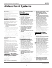
V-PACKING REPLACEMENT
DISASSEMBLY
1. Remove the Fluid Pump as per
"Fluid Pump Disconnect"
instructions on page 11.
2. Unscrew the packing nut and
suction assembly. Push piston rod
out through bottom of pump body.
Remove the upper packings,
belleville springs, tube spacer and
lower packing set using packing
removal tool (PN 331-153).
3. Disassemble and clean all parts for
reassembly. Discard old packings,
adapters and O-Rings.
4. Place piston in block (PN 331-195)
with the 3/8"dowel pin (PN 331-
196) and hold in vise.
NOTE: Do not use smaller diameter pin
to hold piston.
AL2710


