


9
Airless Paint Systems
Operating Instructions and Parts Manual
www.chpower.com
Electrical System (Cont.)
assembly (board) and is installed on
the "P-ZR" terminals. If you are
"Zero Calibrating" a pressure
control assembly presently in the
unit, remove jumper from single
terminal P-ZR and place on both
terminals P-ZR. When Zero
Calibration is complete, replace
jumper on a single terminal of P-ZR.
5. Turn machine "ON" and ensure it is
not cycling.
6. If the yellow zero light on the
electrical board is ON, use an
insulated screwdriver to turn the
"ZERO" trimpot counterclockwise
until the light goes out. Then turn
it clockwise until the light just
comes back on. If so equipped, look
at the LCD Display and if "0000" is
showing the Zero Calibration is
complete. If the display shows more
than "0000", turn the Zero Trimpot
CCW until "0000" is showing. If
"-- -- --" is showing, turn the zero
trimpot CW until "0000" is
displayed.
7. If the yellow light is OFF, turn the
"Zero" trimpot clockwise, just until
the light comes on and stop.
Confirm "0000" is displayed.
NOTE: If the yellow light remains
constantly "ON" or "OFF" during this
calibration, the sensor is defective and
should be replaced.
8. IMPORTANT: When calibration is
complete, move jumper from both
"PZ-R" terminals to single terminal
on P-ZR.
PRESSURE CALIBRATION
1. Complete the ZERO calibration, as
per "ZERO CALIBRATION" prior to
commencing this calibration.
2. Attach a 50', 1/4" airless hose,
airless gun with 0.017 tip and a
5000 psi glycerin filled pressure
gauge to the pump.
3. Place the suction tube into a bucket
of Coro-chek and water.
4. Turn Prime/Pressure Relief Valve to
the prime (open) position.
5. Turn Pressure Control Knob
clockwise until machine starts to
prime.
6. Place the Prime/Pressure Relief
Valve in the pressure (closed)
position.
7. While watching pressure gauge,
slowly adjust the pressure trimpot
(clockwise to increase and
counterclockwise to decrease) until
the maximum static pressure is 3000
psi, with the pressure control knob
fully clockwise. Trigger the gun into
pail several times to ensure pressure
returns to 3000 psi.
LIQUID CRYSTAL DISPLAY (LCD)
CALIBRATION
NOTE: Your unit may or may not be
equipped with an LCD.
1. Complete the "ZERO
CALIBRATION" and "PRESSURE
CALIBRATION" procedures prior to
starting this calibration.
2. Turn Pressure Control Knob up until
system pressure is above 2500 psi
(as indicated on glycerin filled
pressure gauge) and the machine is
not cycling.
3. Use an insulated screwdriver to
adjust the Set trimpot. Turn trimpot
counterclockwise until it clicks, and
then adjust to match pressure
against pressure gauge reading.
4. Move the pressure control knob to
different settings and trigger the
gun several times into pail. This will
ensure that the LCD continues to
match the pressure gauge reading.
PHASE LIMIT TRIMPOT CALIBRATION
(formerly known as the Low Voltage or
Master Voltage Calibration)
1. Attach a 50', 1/4" airless hose,
airless gun with .017 tip and a 5000
psi glycerin filled pressure gauge to
the pump.
2. Place the suction tube into a bucket
of Pump Conditioner and water.
3. Turn pump ON and turn up
Pressure Control until the machine
starts to prime.
4. Place the Prime/Pressure Relief
Valve in the pressure (closed)
position.
5. Pressurize pump to 600 psi.
6. Trigger the gun several times
noting the deadband (the amount
of pressure drop before the pump
rebuilds to set pressure).
7. If deadband is greater than 100 psi,
adjust the low pressure voltage
trimpot so that the deadband is less
than 100 psi and the pressure
increase after the gun trigger is
released is less than 200 psi.
These pressures are guidelines and
may vary slightly from pump to
pump.
8. Reattach Pressure Control Assembly
being careful not to pinch wires.
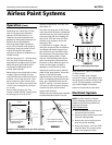
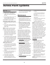
NOTE: The 331-315-99 Pressure Control
Assembly has a reddish brown terminal
labelled “Inhibit Switch.” At all times
there should be a jumper on the two
left terminals, which are the closest to
the “S2” connection. Also on the
Revision E is a terminal labelled “ON-
SL.” This terminal should never have a
jumper on it.
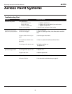
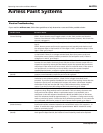
ELECTRICAL TROUBLESHOOTING
A variety of causes can lead to
problems with your sprayer’s electrical
system. Sometimes, it will not start. See
page 15 for a list of possible problems
and solutions to fix them.
AL2710