


Operating Instructions
www.campbellhausfeld.com
10
Welder Operation
(FRONT PANEL SWITCH MUST BE SET TO WELDER POSITION)
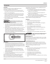
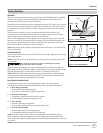
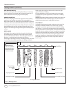
WELDING LEAD ASSEMBLIES
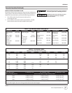
Welding leads assemblies are not included with all units. Use
copper welding cables in the size specified in Table 3.
1. Verify that the surfaces of metals to be joined are free from
dirt, rust, paint, oil, scale or other contaminants. These
contaminants make welding difficult and cause poor welds.
All persons operating this equipment or in the
area while equipment is in use must wear
protective welding gear including: eye protection with proper shade
(minimum shade 10), flame resistant clothing, leather welding gloves,
and full foot protection.
If heating, welding, or cutting materials that are
galvanized, zinc plated, lead, or cadmium plated
refer to the General Safety Information Section for instructions. Toxic
fumes may be created when these materials are heated.
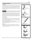
2. Connect the work clamp to the work piece. Make sure
the contact is on bare metal and not obstructed by paint,
varnish, corrosion, or non-metallic materials.
3. Insert the exposed part of the electrode (the end with no
flux) into the jaws of the electrode holder.
4. Set the amperage adjustment knob to the proper
amperage for the electrode diameter. Refer to the electrode
manufacturer for proper current settings.
The electrode holder and rod are electrically
“live” (current potential) when the engine is
running.
5. Position the electrode to begin weld, lower the welding
helmet or position the hand shield, and strike an arc. Adjust
weld amperage as needed.
6. When finished welding, turn engine off and store unit
properly.
DUTY CYCLE / THERMOSTATIC PROTECTION
Welder duty cycle is the percentage of actual weld time that can
occur in a ten minute interval. For example, at a 10% duty cycle,
actual welding can occur for one minute, then the welder must
cool for nine minutes.
Internal components of the alternator are protected from
overheating with an automatic thermal switch.
Compressor Operation
Before starting the compressor, thoroughly read
all component instructions manuals, especially
the engine manual.
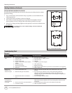
1. Set compressor switch to ON. The compressor clutch will
engage and the pressure switch will disengage the clutch
when the tank pressure reaches the preset maximum
pressure. As air is discharged from the tanks and the tank
pressure falls to the preset minimum pressure, the pressure
switch will engage the clutch again.
2. Adjust the regulator knob to vary the outlet pressure
according to the requirements of the tool(s) being used.
3. Connect air hose(s) to outlet connector(s) and connect
tool(s) to hose(s).
4. An ASME safety valve in the manifold will automatically
release air if the tank pressure exceeds the preset maximum.
5. The discharge tube carries compressed air from the pump
to the check valve. This tube becomes very hot during use.
To avoid the risk of severe burns, never touch the discharge
tube.
6. The check valve allows air to enter the tanks, but prevent air
in the tanks from flowing back into the compressor pump.
7. There is a drain valve in the end of each tank. They have
weighted tubes to draw air / liquid from the bottom of the
tanks. Use these valves to drain moisture from the tanks
daily to reduce the risk of corrosion. Reduce tanks pressure
below 10 PSI, then drain the moisture from the tanks daily
to avoid tank corrosion.
Drain liquid from tank daily.
8. All lubricated compressor pumps discharge some
condensed water and oil with the compressed air. Install
appropriate water / oil removal equipment and controls as
necessary for the intended application.
Failure to install appropriate water / oil removal
equipment may result in damage to machinery
or workpiece.
Do not attach air tools to open end of the hose
until startup is complete and the unit checks
okay.
MOISTURE IN COMPRESSED AIR
Moisture in compressed air will form into droplets as it
comes from an air compressor pump. When humidity is high
or when a compressor is in continuous use for an extended
period of time, this moisture will collect in the tank. When
using a paint spray or sandblast gun, this water will be carried
from the tank through the hose, and out of the gun as droplets
mixed with the spray material.
IMPORTANT: This condensation will cause water spots in a
paint job, especially when spraying other than water based
paints. If sandblasting, it will cause the sand to cake and clog
the gun, rendering it ineffective.
A filter or air dryer in the air line, located as near to the gun as
possible, will help eliminate moisture.