


4
Operating Instructions and Parts Manual
HVLP Paint Sprayers
How Your HVLP
System Works
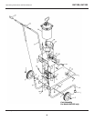
Your turbine system has three
components: the turbine unit, an air
hose and a spray gun. The turbine unit,
when connected to the correct
electrical power supply and powered
on, provides a continuous source of
clean, warm, dry, High Volume Low
Pressure air. The air hose connects the
turbine unit to the spray gun. Air flows
through the hose to the nozzle of the
specially designed spray gun.
Atomization of the coating is achieved
when the air mixes with the stream of
fluid passing through the tip/nozzle.
This low pressure atomization principle
achieves minimum misting (overspray)
to the spray environment.
The turbine blower has one air hose
outlet on the side of the unit and is
designed to run one spray gun. The 4-
stage model has the capability to run
two spray guns at the same time with
an optional “Y” connector. When
using only one spray gun, always be
sure that one outlet is capped.
How Your HVLP
Spray Gun Works
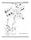
Turbine Spray Guns are bleeder type
spray guns. When the turbine is turned
on, air will constantly flow through the
air cap. This helps makes the
equipment more durable. Air also
flows through the air feed tube in
order to pressurize the cup, and deliver
fluid to the tip/nozzle. When the paint
flow screw is opened and the trigger
pulled back, fluid flows through the
tip/nozzle, mixing with the air flow
delivered from the air cap. The spray
gun projects a fine atomized mist on
your work piece.
www.chpower.com
Pre-Operation
PREPARING TO USE YOUR HVLP
TURBINE SYSTEM
1. Connect the air hose to the turbine.
Pull back the spring loaded quick
disconnect coupler and insert the
male connector on the air hose into
the turbine connector. Release the
ring. Your air hose will be locked
into place. To disconnect, pull back
on the connector to release the air
hose.
If you have just
finished spraying,
the metal coupler at the turbine end
may be hot.
2. Plug the electric cord into a
correctly grounded electrical outlet.
Be sure the electric current is the
correct voltage. If you need to use
an extension cord, be sure it is at
least 12 gauge wire and has a
correctly grounded outlet.
3. Select a safe, well ventilated area
where you will spray your work
piece. Locate your turbine unit
away from the area where you will
be directly spraying. Do not cover
or enclose the turbine. It is
important to draw cool/ambient air
through the unit for optimum
performance. Avoid placing the
!
CAUTION
turbine in a warm environment or
in direct sunlight.
FAMILIARIZING YOURSELF WITH
YOUR SPRAY GUN
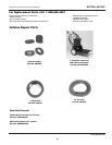
HVLP Spray Gun:
1. Slide the lever to one side,
releasing the cup from the holding
pins on the cup. Reverse the
procedure to install the cup onto
the gun body. Make sure the cup is
secure. Be sure the cup is centered
on the gasket under the top of the
cup.
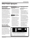
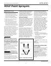
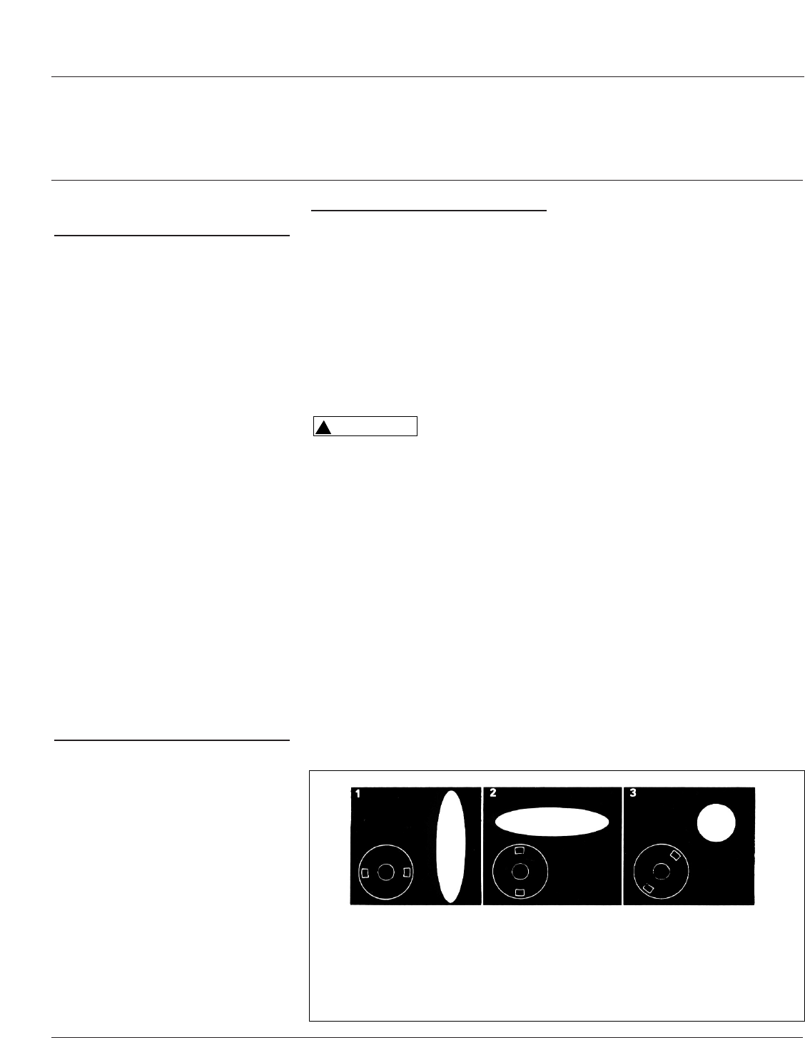
2. Familiarize yourself with the
controls on the spray gun. There
are three main controls: rotating
air cap, material flow knob and air
cap locking ring. Click the rotating
air cap into each position:
horizontal, vertical and 45°. When
the air cap is in the 45° position the
pattern is round. This is useful for
spraying small, narrow pieces of
work. Paint flow will increase when
using the diagonal position. It is
usually necessary to reduce the
paint flow by adjusting the flow
knob. (See Figure 2)
3. Turn the material flow knob
counterclockwise to open or
release more fluid, clockwise to
reduce or close material flow.
HV2100, HV2105
Figure 2 - Material flow knob positions and spray patterns
1. Use this position when spraying across from side to side.
2. Use this position when spraying from top to bottom.
3. Use this position for spotting small objects, corners and sharp angles.