


38 Sp
Manual de Instruccones y Lista de Repuestos
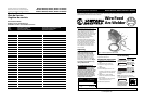
Modelos WF2050, WF2054, WF2057 & WF2058
Notes
General Safety
(Continued)
● Keep the head and face out of the
welding fumes.
● Do not perform electric arc welding
operations on metals that are
galvanized or cadmium plated, or
contain zinc, mercury, or beryllium
without completing the following
precautions:
a. Remove the coating from the base
metal.
b.Make sure that the welding area is
well ventilated.
c. Use an air-supplied respirator.
Extremely toxic fumes are created
when these metals are heated.
The electromagnetic field
that is generated during
arc welding may interfere
with the operation of
various electrical and
electronic devices such as cardiac
pacemakers. Persons using such devices
should consult with their physician prior
to performing any electric arc welding
operations.
● Route the wire gun and work cables
together and secure with tape when
possible.
● Never wrap arc welder cables around
the body.
● Always position the wire gun and
work leads so that they are on the
same side of the body.
● Exposure to electromagnetic fields
during welding may have other
health effects which are not known.
Always be sure
that the welding
area is secure and free of hazards
(sparks, flames, glowing metal or slag)
prior to leaving. Be sure that equipment
is turned off and excess wire is cut off.
Be sure that cables are loosely coiled and
out of the way. Be sure that all metal
and slag has cooled.
ADDITIONAL SAFETY STANDARDS
ANSI Standard Z49.1 from American
Welding Society, 550 N.W. Le June Rd.
Miami, FL 33126
Safety and Health Standards
OSHA 29 CFR 1910, from Superintendent
of Documents, U.S. Government Printing
Office, Washington, D.C. 20402
National Electrical Code
NFPA Standard 70, from National Fire
Protection Association, Batterymarch
Park, Quincy, MA 02269
!
WARNING
!
WARNING
Assembly
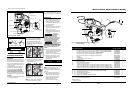
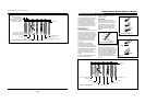
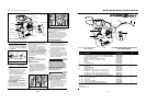
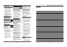
WIRE INSTALLATION
NOTE: Before installing welding wire,
be sure:
a. Diameter of welding wire matches
groove in drive roller on wire feed
mechanism (See Fig. 2). The drive
roller is marked with metric sizes:
.6mm = .024”, .8 - .9mm = .030 –
.035”
b.Wire matches contact tip in end of
gun. (See Fig. 3).
A mismatch on any item could cause the
wire to slip and bind.
NOTE: Always maintain control of loose
end of welding wire to prevent
unspooling.
1. Verify unit is off and open door
panel to expose wire feed
mechanism.
2. Remove the spool quick lock by
pushing in and rotating 1/4 turn
counterclockwise. Then remove
knob, spring and spool spacer.
3. Flip tensioning screw down on drive
mechanism. This allows initial
feeding of wire into gun liner by
hand.
4. Install wire spool onto spindle so
wire can come off spool on the end
closest to the wire feed guide tube.
Do not cut the wire loose yet.
Install spool spacer, spring and quick
lock knob by pushing in and turning
knob 1/4 rotation clockwise.
5. Hold wire and cut the wire end from
spool. Do not allow wire to
unravel. Be sure end of wire is
straight and free of burrs.
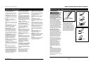
6. Feed wire through wire feed guide
tube, over the groove in drive roller
and into gun liner. Flip tensioning
screw up and adjust tension by rotating
tensioning screw knob. Do not
overtighten.
7. Remove nozzle by turning counter-
clockwise, then unscrew contact tip
from end of welding torch (See
Figure 3). Plug welder into a proper
power supply receptacle.
8. Turn on welder and set wire speed
rate to 10. Activate gun trigger until
wire feeds out past the torch end.
Turn welder off.
9. Carefully slip contact tip over wire
and screw tip into torch end. Install
nozzle by turning clockwise (See
Figure 3). Cut wire off approximately
1/4 inch from nozzle end.
3
Safe Handling of Compressed Gases
in Cylinders
CGA Pamphlet P-1, from Compressed
Gas Association, 1235 Jefferson Davis
Highway, Suite 501, Arlington, VA 22202
Code for Safety in Welding and
Cutting
CSA Standard W117.2, from Canadian
Standards Association, Standards Sales,
178 Rexdale Boulevard, Rexdale,
Ontario, Canada M9W 1R3
Cutting And Welding Processes
NFPA Standard 51B, from National Fire
Protection Association, Batterymarch
Park, Quincy, MA 02269
Safe Practices For Occupational And
Educational Eye And Face Protection
ANSI Standard Z87.1, from American
National Standards Institute, 1430
Broadway, New York, NY 10018
Refer to the Material Safety Data Sheets
and the manufacturers instructions for
metals, wire, coatings and cleaners.
Installation
LOCATION
Selecting the proper location can
significantly increase performance,
reliability and life of the arc welder.
● For best results locate the welder in
an environment that is clean and dry.
Dust and dirt in the welder retain
moisture and increase wear of
moving parts.
● Place the welder in an area that
provides at least twelve inches (305
mm) of ventilation space at both the
front and rear of the unit. Keep all
obstructions away from this
ventilation space.
● Store flux cored wire in a clean, dry
location with low humidity to reduce
oxidation.
● The receptacle used for the welder
must be properly grounded and the
welder must be the only load on the
power supply circuit. Refer to the
Circuit Amps chart on page 1 for
correct circuit capacity.
● The use of an extension cord is not
recommended for electric arc
welding machines. The voltage drop
in the extension cord may
significantly degrade the
performance of the welder.
Models WF2050, WF2054, WF2057 & WF2058
www.chpower.com