


34 Sp
Manual de Instruccones y Lista de Repuestos
7
air from reacting with the molten metal.
Once the weld cools to the point that it
is no longer glowing red, the slag can be
removed. Removal is done with a
chipping hammer. Lightly tap the slag
with the hammer and break it loose
from the weld bead. The final clean-up is
done with a wire brush. When making
multiple weld passes, remove the slag
before each pass.
WELDING POSITIONS
Four basic welding positions can be used;
flat, horizontal, vertical, and overhead.
Welding in the flat position is easier than
any of the others because welding speed
can be increased, the molten metal has
less tendency to run, better penetration
can be achieved, and the work is less
fatiguing. Welding is performed with
the wire at a 45º travel angle and 45º
work angle.
Other positions require different
techniques such as a weaving pass,
circular pass, and jogging. A higher skill
level is required to complete these welds.
Overhead welding is the least desirable
position as it is the most difficult and
dangerous. Heat setting and wire
selection will vary depending upon the
position.
All work should be performed in the flat
position if possible. For specific
applications, consult an arc welding
technical manual.
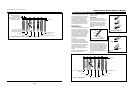
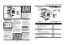
WELD PASSES
Sometimes more then one pass is
necessary to fill the joint. The root pass is
first, followed by filler passes and the
cover pass (See Fig. 8). If the pieces are
thick, it may be necessary to bevel the
edges that are joined at a 60º angle.
Remember to remove the slag before
each pass.
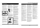
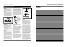
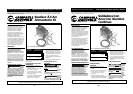
PUSH VS PULL TECHNIQUE
The type and thickness of the work piece
dictate which way to point the gun
nozzle. For thin materials (18 gauge and
up), the nozzle should point out in front
of the weld puddle and push the puddle
across the workpiece. For thicker steel,
the nozzle should point into the puddle
to increase weld penetration. This is
called backhand or pull technique (See
Figure 10).
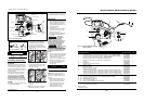
Figure 8 - Fillet Welds (60˚ Bevel)
Models WF2050, WF2054, WF2057 & WF2058
Welding Guidelines (Continued)
Cover
Root
Filler
www.chpower.com
PULL
Figure 10
Figure 9 - Multiple Weld Passes
PUSH
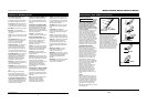
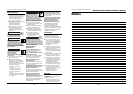
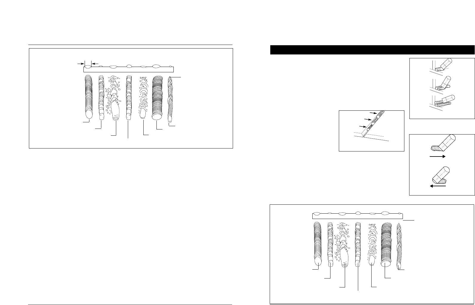
Wire speed too fast
Heat too high
Wire speed too slow
Heat too low
Travel speed too low
Travel speed too fast
Normal heat, wire speed,
travel speed
Base metal
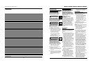
Figure 11 - Weld Appearance
Metal Básico
Figura 11 - Apariencia de la soldadura
Velocidad de alimentación muy rápida
Corriente muy alta
Velocidad de desplazamiento muy lenta
Corriente muy baja
Velocidad muy lenta
Velocidad muy rápida
Corriente, velocidad de
alimentación y velocidad de
desplazamiento normales
A
Nota: El ancho (A) del
reborde debe ser
aproximadamente el doble
del diámetro de la varilla de
electrodo que se use.