


37 Sp
Modelos WF2050, WF2054, WF2057 & WF2058
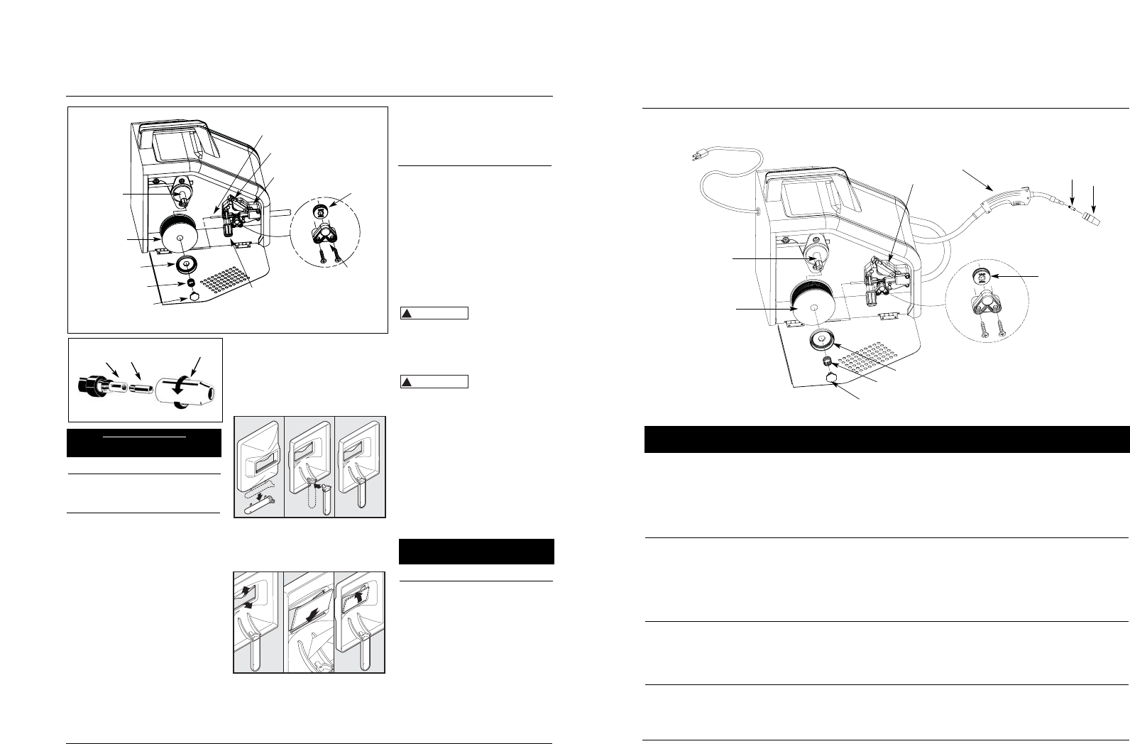
5
1
2
3
4
9
8
7
6
10
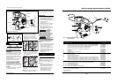
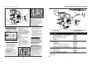
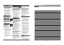
Figure 12 - Modèlos WF2050, WF2054,
WF2057 & WF2058
No. de Ref. Descripción No. del repuesto Ctd.
1 Ensamble de soplete y manguera (fundente revestido, 2,44 m, WF2050 & WF2057) WC403650AV 1
Ensamble de soplete y manguera (fundente revestido, 3,05 m, WF2054 & WF2058) WC404000AV 1
2 Punta de contacto - 0,035” (0,9 mm, 3,05 m, WF2054 & WF2058) WT501400AV 1
Punta de contacto opcional – 0,030” (0,8 mm) Paquete de 4 WT501300AJ †
Punta de contacto opcional – 0,035” (0,9 mm) Paquete de 4 WT501400AJ †
3 Boquilla WT502100AV 1
4 Portabobinas WC500805AV 1
5 Ensamble de la placa de conducción WC500800AJ 1
6 Vástago y rejilla WC707018AV 1
7 Retén de la bobina WC707024AV 1
8 Resorte del retén de la bobina WC707026AV 1
9 Anillo del retén de la bobina WC707023AV 1
10 Alambre de soldar c/fundente – 0,030” (0,8 mm) Bobina de 2 lb (0,9 kg) (E71T-GS) WE200001AV †
Alambre de soldar c/fundente – 0,030” (0,8 mm) Bobina de 10 lb. (4,54 kg) (E71T-GS) WE201000AV †
Alambre de soldar c/fundente – 0,035” (0,9 mm) Bobina de 2 lb. (0,9 kg) (E71T-GS) WE200501AV †
Alambre de soldar c/fundente – 0,035” (0,9 mm) Bobina de 10 lb. (4,54 kg) (E71T-GS) WE201500AV †
11 ▲ Máscara de mano (no se incluyen lentes) (WF2050 & WF2058) WC801700AV 1
12 ▲ Lentes oscuros (para máscara de mano) (WF2050, WF2054 & WF2058) WC801100AV 1
13 ▲ Martillo/cepillo cincelador WC803400AV 1
14 ▲ Etiqueta adhesiva de seguridad DK688509AV 1
15 ▲ Pinza de tierra (WF2050) WC100300AV 1
▲ Pinza de tierra (WF2054, WF2057 & WF2058) WC100600AV 1
16 ▲ Guantes para soldar (sólo WF2054, WF2057 & WF2058) WT200501AV 1
17 ▲ Casco de soldar (sólo WF2057) WT100500AV 1
▲ No se muestran
† Accesorio opcional
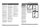
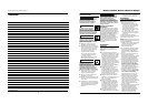
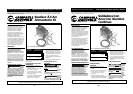
HANDSHIELD
1. Cut detachable handle (WF2050,
WF2054 & WF2058 only; WF2057 is
supplied with a fully assembled
helmet) away from shield. Trim the
excess plastic to remove sharp edges
(See Figure 4).
2. To attach the handle, place shield on
a flat surface and press handle into
place (See Figure 4).
3. Insert filter lens exactly as shown in
Figure 5.
NOTE: If you have never welded before
or have little experience, a full face
4
Operating Instructions and Parts Manual
Assembly (Continued)
DUTY CYCLE / THERMOSTATIC
PROTECTION
Welder duty cycle is the percentage of
actual weld time that can occur in a ten
minute interval. For example, at a 20%
duty cycle, actual welding can occur for
two minutes, then the welder must cool
for eight minutes.
Internal components of this welder are
protected from overheating with an
automatic thermal switch. A yellow
lamp is illuminated on the front
panel if the duty cycle is exceeded.
Welding operations may continue when
the yellow lamp is no longer illuminated.
POLARITY
This welder is configured for DCEN, direct
current electrode negative.
helmet is recommended. Both hands
are needed to stabilize and control the
angle and arc length of the electrode.
Operation
1. Be sure to read, understand, and
comply with all precautions in the
General Safety Information section.
Be sure to read the entire section
entitled Welding Guidelines prior to
using this equipment.
2. Turn welder off.
3. Verify that the surfaces of metals to
be joined are free from dirt, rust,
paint, oil, scale or other
contaminants. These contaminants
make welding difficult and cause
poor welds.
All persons
operating this
equipment or in the area while
equipment is in use must wear
protective welding gear including: eye
protection with proper shade, flame
resistant clothing, leather welding
gloves, and full foot protection.
If heating,
welding, or cutting
materials that are galvanized, zinc
plated, lead, or cadmium plated refer to
the General Safety Information Section
for instructions. Extremely toxic fumes
are created when these metals are
heated.
4. Connect the work clamp to the work
piece or workbench (if metal). Make
sure the contact is secure. Avoid
surfaces with paint, varnish,
corrosion, or non-metallic materials.
5. Position the Heat Selector on the
front panel to the desired setting
(See decal inside wire feed
compartment).
NOTE: These settings are general
guidelines only. Heat setting may vary
according to welding conditions and
materials.
6. Rotate the Wire Speed Control to
setting number 5 to start with, then
adjust as needed after test weld.
7. Plug the input cord into a proper
voltage receptacle with proper
circuit capacity (See circuit
requirements on front page).
!
WARNING
!
WARNING
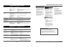
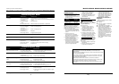
Contact Tip Markings
Mark Wire Size
0.8 mm 0.030”
0.9 mm 0.035”
www.chpower.com
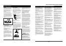
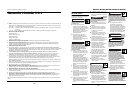
Torch
Diffuser
Contact Tip
Nozzle
Figure 3 - Torch Nozzle
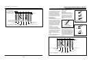
Spindle
Welding wire
Tensioner ring
Tension spring
Retainer
Tensioner knob
Guide tube
Tensioner arm
Drive deck
Roller
support
Drive
roller
Figure 2 - Weld Wire Routing
Figure 4
Figure 5
Metal Heat
Thickness Setting
14 - 18 Gauge Low
Thicker Than 14 Gauge High