


Preparación del gas protector
¡El
manipu-
leo y mantenimiento incorrecto de los
cilindros y reguladores de gas
comprimido puede ocasionar lesiones
graves o la muerte! Siempre asegure los
cilindros de gas al soporte del tanque, a
la pared u otro soporte fijo para evitar
que los cilindros se caigan. Lea,
entienda y siga todas las advertencias
del gas comprimido y equipo en las
instrucciones de seguridad.
AVISO: No se requiere gas protector si se
utiliza soldadura de núcleo fundente.
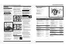
TIPOS DE GAS
Existen tres tipos de gas que
generalmente se utilizan para la soldadura
por arco de metal de gas: 100% de argón,
una mezcla de 75% de argón y 25% de
dióxido de carbono (C25) o 100% de
dióxido de carbono.
Use
SOLAMENTE el tipo de gas recomendado
para su soldadora. Use SOLAMENTE un
tipo de gas inerte, no inflamable. Si no
lo hace podría ocasionarse una situación
muy peligrosa.
NOTA: No se recomienda el 100% de
dióxido de carbono debido a que se
producen cordones de soldadura
inadecuados.
Se recomienda la mezcla 75/25 para
soldadura de acero general. Para
soldadura de aluminio, utilice 100% de
argón. Los cilindros de cualquiera de estos
dos tipos los puede obtener en su punto
de venta local de suministros para
soldadura. Asegure el cilindro en su lugar
en su máquina soldadora u otro soporte
para evitar que se caiga.
Cómo obtener el tipo correcto de
gas. El gas que use en cualquier
aplicación de soldadura para su
soldadora debe ser DE TIPO INERTE, NO
INFLAMABLE. Puede obtener el tipo de
gas necesario en un distribuidor de gas
para soldaduras cercano (con frecuencia
los encuentra en las páginas amarillas
bajo "Soldadoras" o "Equipos para
soldaduras").
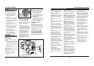
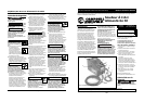
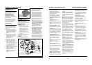
REGULADOR
Con el WG2060 se proporciona un
regulador ajustable sin calibradores. El
regulador proporcionado con el WG2064
incluye dos calibradores. El regulador
brinda una presión de gas protector y
velocidad de circulación constantes
durante el proceso de soldadura. Cada
regulador ha sido diseñado para ser
utilizado con un gas específico o una
mezcla de gases. El argón y la mezcla
de argón utiliza el mismo tipo de
!
PELIGRO
!
PELIGRO
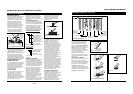
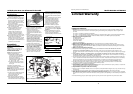
HERRAMIENTAS NECESARIAS:
Destornillador Phillips y llave de cubo
de 10 mm.
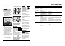
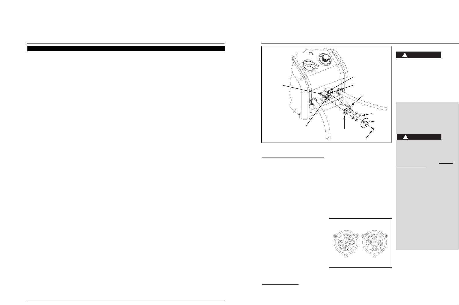
1. Desenchufe el cable de corriente de
la toma de corriente.
2. Retire los tornillos de la tapa y la
tapa de polaridad.
3. Retire las cuatro tuercas de los
pasadores de polaridad.
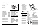
4. Tire la barra de polaridad hacia
afuera y gírela 90°. Vuelva a
colocarla alineando la ranura con la
marca correcta de la caja de
polaridad. La marca superior
derecha indica la posición MIG, la
marca inferior izquierda indica la
posición Fundente. (vea la figura 4c)
5. Vuelva a colocar las cuatro tuercas y
ajústelas de modo seguro.
6. Vuelva a colocar la tapa de
polaridad y los tornillos de
polaridad.
7. Asegúrese de que la flecha de la
tapa de polaridad apunte a la
configuración deseada.
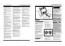
Ensamblaje
(Continuación)
de las agujas del reloj mientras la
empuja hacia el soplete (Ver Figura 4).
Corte el cable aproximadamente 1/4 de
pulgada del extremo de la boquilla.
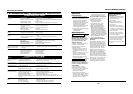
CICLO DE TRABAJO / PROTECCIÓN CON
TERMOSTATO
El ciclo de trabajo de la soldadora es el
porcentaje del tiempo de soldadura
real que puede ocurrir en un intervalo
de diez minutos. Por ejemplo, en un
ciclo de trabajo del 20%, la soldadura
real puede ocurrir por dos minutos,
luego la soldadora debe dejarse enfriar
por ocho minutos.
Los componentes internos de esta
soldadora están protegidos contra
recalentamiento con un interruptor
térmico automático. Una luz amarilla se
enciende en el panel delantero si se
excede del ciclo de trabajo. Las
operaciones de soldadura pueden
continuar cuando la luz amarilla ya no
está encendida.
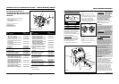
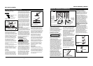
POLARIDAD
El alambre para soldadura MIG necesita
un electrodo positivo. El alambre para
soldadura con fundente necesita un
electrodo negativo. La configuración de
fábrica de la soldadora es de alambre
para soldadura con fundente.
Para cambiar la polaridad
(vea la figura 4b)
NOTA: La flecha en la Tapa de
polaridad apunta a la configuración
actual de la polaridad.
33 Sp
Modelos WG2060 y WG2064
12
Wire Feed Arc Welder
AC or Alternating Current - electric
current that reverses direction
periodically. Sixty cycle current travels
in both directions sixty times per
second.
Arc Length - the distance from the
end of the electrode to the point
where the arc makes contact with the
work surface.
Base Metal - the material to be
welded.
Butt Joint - a joint between two
members aligned approximately in the
same plane.
Crater - a pool, or pocket, that is
formed as the arc comes in contact
with the base metal.
DC or Direct Current - electric
current which flows only in one
direction. The polarity (+ or -)
determines which direction the current
is flowing.
DC Reverse Polarity - occurs when
the electrode holder is connected to
the positive pole of the welding
machine. Reverse Polarity directs more
heat into melting the electrode rather
than the work piece. It is used on
thinner material.
DC Straight Polarity - occurs when
the electrode holder is connected to
the negative pole of the welding
machine. With straight polarity more
heat is directed to the work piece for
better penetration on thicker material.
Electrode - a coated metal wire
having approximately the same
composition as the material being
welded.
Fillet Weld - approximately a triangle
in cross-section, joining two surfaces at
right angles to each other in a lap, T or
corner joint.
Flux - a coating, when heated, that
produces a shielding gas around the
welding area. This gas protects the
parent and filler metals from
impurities in the air.
Flux Cored Arc Welding (FCAW) -
also called Gasless, is a welding process
used with a wire-feed welding
machine. The weld wire is tubular
with flux material contained inside for
shielding.
Gas Metal Arc Welding (GMAW) -
also called MIG, is a welding process
used with a wire feed welding
machine. The wire is solid and an inert
gas is used for shielding.
Gas Tungsten Arc Welding (GTAW)
- also called TIG, is a welding process
used with welding equipment with a
high frequency generator. The arc is
created between a non-consumable
tungsten electrode and the work
piece. Filler metal may or may not be
used.
Lap Joint - a joint between two
overlapping members in parallel
planes.
Open Circuit Voltage (OCV) - the
voltage between the electrode and the
work clamp of the welding machine
when no current is flowing (not
welding). The OCV determines how
quickly the arc is struck.
Overlap - occurs when the amperage
is set too low. In this instance, the
molten metal falls from the electrode
without actually fusing into the base
metal.
Porosity - gas pockets, or cavities,
formed during weld solidification.
They weaken the weld.
Penetration - the depth into the work
piece that has been heat effected by
the arc during the welding process. A
good weld achieves 100% penetration
meaning that the entire thickness of
the work piece has been heated and
resolidified. The heat effected area
should be easily seen on the opposite
side of the weld.
Shielded Metal Arc Welding
(SMAW) - also called Stick, is a
welding process with uses a
consumable electrode to support the
arc. Shielding is achieved by the
melting of the flux coating on the
electrode.
Slag - a layer of flux soot that protects
the weld from oxides and other
contaminants while the weld is
solidifying (cooling). Slag should be
removed after weld has cooled.
Spatter - metal particles thrown from
the weld which cool and harden on
the work surface. Spatter can be
minimized by using a spatter resistant
spray on the work piece before
welding.
Tack Weld - weld made to hold parts
in proper alignment until final welds
are made.
Travel Angle - the angle of the
electrode in the line of welding. It
varies from 5º to 45º depending on
welding conditions.
T Joint - made by placing the edge of
one piece of metal on the surface of
the other piece at approximately a 90º
angle.
Undercut - a condition that results
when welding amperage is too high.
The excessive amperage leaves a
groove in the base metal along both
sides of the bead which reduces the
strength of the weld.
Weld Pool or Puddle - a volume of
molten metal in a weld prior to its
solidification as weld metal.
Weld Bead - a narrow layer or layers
of metal deposited on the base metal
as the electrode melts. Weld bead
width is typically twice the diameter of
the electrode.
Work Angle - the angle of the
electrode from horizontal, measured
at right angles to the line of welding.
Glossary of Welding Terms
www.chpower.com
Models WG2060 and WG2064
Figura 4b
Caja de
polaridad
Marca de
fundente
Barra de polaridad
Tuercas
Tornillo de la tapa
Tapa de
polaridad
Ranura
Pasadores de polaridad
Marca de MIG
Figura 4c
Posición MIG
Posición Fundente
Superior derecha-
marca de MIG
Inferior derecha-
marca de fundente