


37 Sp
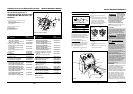
Modelos WG2060 y WG2064
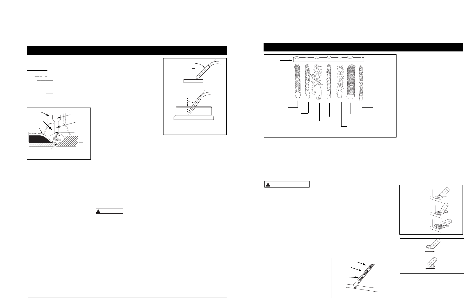
Cuando la velocidad es demasiado rápida,
la perla es delgada y las ondulaciones de
la perla son en punta tal como se
muestra. Cuando la velocidad es
demasiado lenta, el metal de soldadura se
acumula y la perla es alta y ancha. Para
aluminio, la velocidad del alambre
generalmente se establece más alta.
REMOCIÓN DE LA ESCORIA
(SÓLO CABLE DE NÚCLEO FUNDENTE)
Utilice
anteojos
de seguridad ANSI (Norma ANSI Z87.1) y
ropa de protección cuando remueva la
escoria. La escoria caliente que salta
puede causar lesiones personales a
cualquier persona en el área.
Luego de completar la soldadura, espere
que las secciones soldadas se enfríen. Un
revestimiento protector llamado escoria
cubre ahora la perla de soldadura que
evita que los contaminantes en el aire
reaccionen con el metal fundido. Una vez
que la soldadura se enfría al punto que
ya no está rojo incandescente, se puede
retirar la escoria con una rebabadora.
Golpee ligeramente la escoria con la
rebabadora y rómpala aflojándola de la
perla de soldadura. La limpieza final se
realiza con un cepillo de alambre. Cuando
realice varias pasadas de soldadura, retire
el desecho antes de cada pasada.
POSICIONES DE SOLDADURA
Se pueden utilizar cuatro posiciones de
soldadura básicas: plana, horizontal,
vertical y sobre la cabeza. Soldar en la
posición plana es más fácil que cualquiera
de las otras porque se puede aumentar la
velocidad de soldadura, la fundición
tiende menos a correrse, se puede lograr
!
ADVERTENCI
A
Pautas de Soldadura (Continuación)
una mejor penetración y el trabajo es
menos agotador. La soldadura se realiza
con el cable a un ángulo de propagación
de 45° y un ángulo de trabajo de 45°.
Las demás posiciones requieren diferentes
técnicas tales como una pasada de vaivén,
pasada circular y golpecitos. Se requiere
de un mayor nivel de experiencia para
realizar estas soldaduras.
La soldadura sobre la cabeza es la
posición menos deseable ya que es la más
difícil y peligrosa. El ajuste del calor y la
selección del cable variarán dependiendo
de la posición.
Todos los trabajos deben realizarse en la
posición plana si es posible. Para
aplicaciones específicas, consulte un
manual técnico de soldadura por arco.
PASADAS DE SOLDADURA
Algunas veces se requiere más de una
pasada para rellenar la unión. La pasada
de fondo es la primera, seguida por las
pasadas de relleno y la pasada de
cubierta. Si las piezas son gruesas, quizás
sea necesario biselar los bordes que están
unidos con un ángulo de 60°.Recuerde
retirar el desecho antes de cada pasada
para el proceso sin gas.
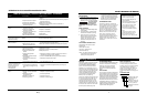
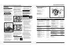
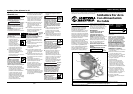
Calor,
velocidad del
cable y
velocidad de
propagación
normales
Calor demasiado bajo
Calor demasiado alto
Velocidad del
cable
demasiado
rápida
Velocidad del cable
demasiado lenta
Velocidad de
propagación
demasiado lenta
Velocidad de
propagación
demasiado
rápida
Metal
de Base
Figura 10 - Aspecto de la Soldadura
SOLDADURA DE ALUMINIO
Cualquier superficie de aluminio que
deba ser soldada, se debe limpiar
minuciosamente con un cepillo de acero
inoxidable para eliminar cualquier resto
de oxidación que pueda haber sobre la
superficie de la soldadura y de la
conexión a tierra. Se debe utilizar 100%
argón cuando se suelda aluminio. Si no se
utiliza argón, es muy improbable que se
logre la penetración metálica. Cuando se
suelda aluminio, se recomienda el
recubrimiento de Teflon
®
para el
cable, el rodillo de alimentación con
ranura lisa, y puntas de contacto de
aluminio. Campbell Hausfeld ofrece
estas piezas en el Kit WT2531. Llame al
800-746-5641 para colocar un pedido.
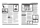
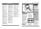
TÉCNICA DE EMPUJE VERSUS TÉCNICA
DE JALADO
El tipo y espesor de la pieza de trabajo
determina hacia qué lado apuntar la
boquilla de la pistola. Para materiales
delgados (indicador 18 para arriba) y todo
aluminio, la boquilla deberá apuntar
frente a la mezcla de soldadura y empujar
esta mezcla a través de la pieza de
trabajo. Para acero más grueso, la
boquilla deberá apuntar hacia la mezcla
para aumentar la penetración de la
soldadura. A esto se le conoce como la
técnica del revés o técnica de empuje. (ver
Figura 13).
Figura 11 - Pasadas de soldadura
Cubierta
Relleno
Fondo
Figura 12 - Pasadas
de soldadura
múltiples
EMPUJE
JALADO
Figura 13
Wire Feed Arc Welder
8
Welding Guidelines (Continued)
AWS E71T-GS or E71T-11 is
recommended for this welder.
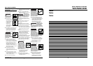
SOLID WIRE
ER - 70S - 6
Weld strength, times
1,000 PSI
Solid wire
Wire composition
ER-70S6 is recommended for this
welder.
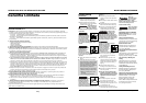
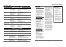
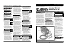
WELD ANGLE
Weld angle is the angle at which the
nozzle is held during the welding
process. Using the correct angle ensures
proper penetration and bead formation.
As different welding positions and weld
joints become necessary, nozzle angle
becomes an increasingly important
factor in obtaining a satisfactory weld.
Weld angle involves two positions -
travel angle and work angle.
Travel angle is the angle in the line of
welding and may vary from 5º to 45º
from the vertical, depending on welding
conditions.
Work angle is the angle from
horizontal, measured at right angles to
the line of welding. For most
applications, a 45º travel angle and 45º
work angle is sufficient. For specific
applications, consult an arc welding
handbook.
WIRE SPEED
The wire speed is controlled by the
knob on the front panel. The speed
needs to be “tuned” to the rate at
which the wire is being melted in the
arc. Tuning is one of the most critical
functions of wire feed welding. Tuning
should be performed on a scrap piece
of metal the same type and thickness as
that to be welded. Begin welding with
one hand “dragging” the gun nozzle
across the scrap piece while adjusting
the wire speed with the other hand.
Too slow of speed will cause sputtering
and the wire will burn up into the
contact tip. Too fast a speed will also
cause a sputtering sound and the wire
will push into the plate before melting.
A smooth buzzing sound indicates the
wire speed is properly tuned. Repeat
the tuning procedure each time there is
a change in heat setting, wire diameter
or type, or work piece material type or
thickness. For Aluminum, wire speed is
typically set higher (7-9 speed range).
TRAVEL SPEED
The travel speed is the rate at which the
torch is moved across the weld area.
Factors such as diameter and type of weld
wire, amperage, position, and work piece
material thickness all affect the speed of
travel necessary for completing a good
weld (See Fig. 10). When the speed is too
fast, the bead is narrow and bead ripples
are pointed as shown. When the speed is
too slow, the weld metal piles up and the
bead is high and wide. For Aluminum,
travel speed is typically faster.
SLAG REMOVAL
(FLUX-CORED WIRE ONLY)
Wear ANSI
approved safety
glasses (ANSI Standard Z87.1) and
protective clothing when removing
slag. Hot, flying debris can cause
personal injury to anyone in the area.
After completing the weld, wait for the
welded sections to cool. A protective
coating called slag now covers the weld
bead which prevents contaminants in
the air from reacting with the molten
metal. Once the weld cools to the point
that it is no longer glowing red, the
slag can be removed. Removal is done
with a chipping hammer. Lightly tap
the slag with the hammer and break it
loose from the weld bead. The final
clean-up is done with a wire brush.
When making multiple weld passes,
remove the slag before each pass.
!
WARNING
WELDING POSITIONS
Four basic welding positions can be used;
flat, horizontal, vertical, and overhead.
Welding in the flat position is easier than
any of the others because welding speed
can be increased, the molten metal has less
tendency to run, better penetration can be
achieved, and the work is less fatiguing.
Welding is performed with the wire at a
45º travel angle and 45º work angle.
Other positions require different
techniques such as a weaving pass,
circular pass, and jogging. A higher skill
level is required to complete these welds.
Overhead welding is the least desirable
position as it is the most difficult and
dangerous. Heat setting and wire selection
will vary depending upon the position.
All work should be performed in the
flat position if possible. For specific
applications, consult an arc welding
technical manual.
WELD PASSES
Sometimes more then one pass is
necessary to fill the joint. The root pass
is first, followed by filler passes and the
cover pass. If the pieces are thick, it may
be necessary to bevel the edges that
are joined at a 60º angle. Remember to
remove the slag before each pass for
the FCAW process.
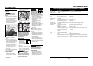
TRAVEL ANGLE
WORK ANGLE
5º - 45º
5º - 45º
Figure 9 - Weld Angle
www.chpower.com
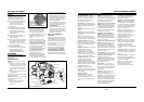
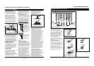
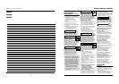
Slag
Weld
Wire
Flux
(Gasless
only)
Work Piece
Shielding
Gas
Contact
Tip
Crater
Nozzle
Figure 8 - Weld Components