


39 Sp
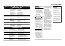
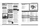
Table de Detección y Solución de Problemas - Soldadura
Síntoma Causas Posibles Medida Correctiva
Reborde es muy
delgado en algunos
sitios
Reborde es muy
grueso en algunos
sitios
Los bordes de la
soldadura están
disparejos
La soldadura no
penetra el metal que
desea soldar
El electrodo salpica y
se pega
1. La velocidad de desplazamiento varia o
es rápida
2. El nivel del amperaje es muy bajo
1. La velocidad de desplazamiento varia o
es muy lenta
2. El nivel del amperaje es muy alto
1. La velocidad de desplazamiento es
muy rápida
2. La velocidad de alimentación es muy
rápida
3. El nivel del amperaje es muy alto
1. La velocidad de desplazamiento no es
consistente
2. El nivel de energía es muy bajo
3. Se terminó el gas o el nivel de gas es
muy bajo
4. Está usando el gas incorrecto
(aluminio)
5. El cordón de extensión es muy largo
6. (Aluminio) Posiblemente se están
formando residuos de óxido en la
superficie
1. El alambre está húmedo
2. La velocidad del alambre está muy
rápida
3. Está utilizando el alambre inadecuado
4. Se terminó el gas o el nivel de gas es
muy bajo
1. Debe reducirla y mantenerla constante
2. Debe aumentarlo
1. Debe aumentarla y mantenerla constante
2. Debe bajarlo
1. Debe reducirla
2. Debe aumentarla
3. Debe bajarlo
1. Disminuya la velocidad y manténgala constante
2. Aumente el nivel de energía de suministro
3. Use gas, para soldar con gases inertes (MIG) o llene la boqtella
4. Use sólo 100% Argón
5. Nunca use cordones de extensión de más de 6,10 m (20 pies)
6. Limpie bien la superficie con un cepillo de acero inoxidable
sólamente
1. Use un alambre seco y siempre debe almacenarlo e un sitio
seco
2. Reduzca la velocidad del alambre
3. Use alambre de fundente revestido cuando no esté utilizando
gases
4. Use gas, para soldar con gases inertes (MIG) o llene la boqtella
Modelos WG2060 y WG2064
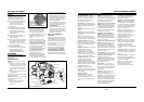
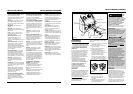
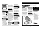
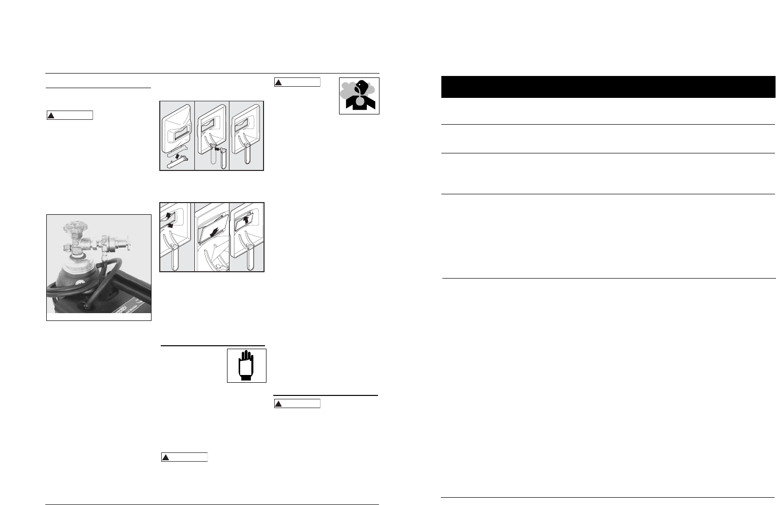
2. To attach the handle, place shield on
a flat surface and press handle into
place – see Figure 6.
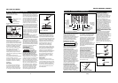
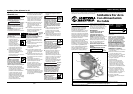
3. Insert filter lens exactly as shown in
Figure 7.
NOTE: If you have never welded
before or have little experience, a
full face helmet is recommended.
Both hands are needed to stabilize
and control the angle and arc
length of the torch.
Operation
1. Be sure to read,
understand and comply
with all precautions in
the General Safety
Information section. Be
sure to read entire "Welding
Guidelines" section before using this
equipment.
2. Turn welder off.
3. Verify surfaces of metals to be joined
are free from dirt, rust, paint, oil,
scale or other contaminants. These
contaminants make welding difficult
and cause poor welds.
All persons
operating this
equipment or in the area while
equipment is in use must wear
protective welding gear including: eye
protection with proper shade, flame
resistant clothing, leather welding
gloves and full foot protection.
!
WARNING
Assembly (Continued)
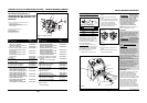
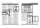
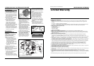
HOSE AND REGULATOR HOOKUP
PROCEDURE
Cylinder gas is under high pressure.
Point cylinder outlet away from
yourself and any bystanders before
opening.
1. With cylinder securely installed, stand
on side of cylinder opposite cylinder
outlet then remove cylinder cap and
open valve slightly by turning
counterclockwise. When gas is
emitted from cylinder, close valve by
turning clockwise. This will blow out
dust or dirt that may have
accumulated around valve seat.
2. Install regulator onto cylinder valve.
Tighten stem nut securely to gas
valve.
3. Install one end of gas hose to fitting
on the top of welder and other end of
hose to fitting on regulator using hose
clamps on each connection. Make sure
gas hose is not kinked or twisted.
4. While standing opposite cylinder
outlet, slowly open cylinder valve.
Inspect for leaks in the connections.
5. Pull trigger on gun to allow gas to
flow. Adjust gas regulator to
maximum flow by rotating clockwise.
Release trigger.
6. Remember to close gas cylinder valve
when finished welding.
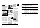
Handshield Assembly
1. Cut detachable handle away from
shield. Trim the excess plastic to
remove sharp edges – see Figure 6.
!
WARNING
6
Wire Feed Arc Welder
If heating, welding or
cutting galvanized, zinc
plated, lead, or cadmium
plated materials, refer to
the General Safety
Information Section for instructions.
Extremely toxic fumes are created when
these metals are heated.
4. Connect work clamp to work piece or
workbench (if metal). Make sure
contact is secure. Avoid surfaces with
paint, varnish, corrosion or non-
metallic materials.
5. Rotate Wire Speed Control to setting
number 5 to start, then adjust as
needed after test.
6. Plug power cord into a proper
voltage receptacle with proper circuit
capacity (see circuit requirements on
front page).
7. Switch welder on to desired heat
setting per decal inside wire feed
compartment.
NOTE: These settings are general
guidelines only. Heat setting may vary
according to welding conditions and
materials.
8. Verify wire is extended 1/4” from
contact tip. If not, squeeze trigger to
feed additional wire, release trigger,
turn welder off, and cut wire to
proper length. Then, switch back on
to desired heat setting.
9. Position wire feed gun near work
piece, lower welding helmet by
nodding head or positioning the hand
shield, and squeeze gun trigger. Adjust
heat setting and wire speed as needed.
10. When finished welding, turn welder
off and store properly.
Maintenance
Disconnect power
supply and turn
machine off before inspecting or
servicing any components. Keep wire
compartment cover closed at all times
unless wire needs to be changed.
BEFORE EVERY USE:
1. Check condition of weld cables and
immediately repair or replace any
cables with damaged insulation.
2. Check condition of power cord and
immediately repair or replace any
cord if damaged.
!
WARNING
!
WARNING
MANUAL
www.chpower.com
Figure 5 - Hose and Regulator Hookup
Figure 6
Figure 7