


WIRE TYPE AND SIZE
The correct choice of wire type
involves a variety of factors, such as
welding position, work piece material
type, thickness, and condition of
surface to be welded. The American
Welding Society, AWS, has set up
certain requirements for each type of
wire.
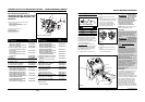
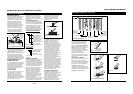
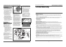
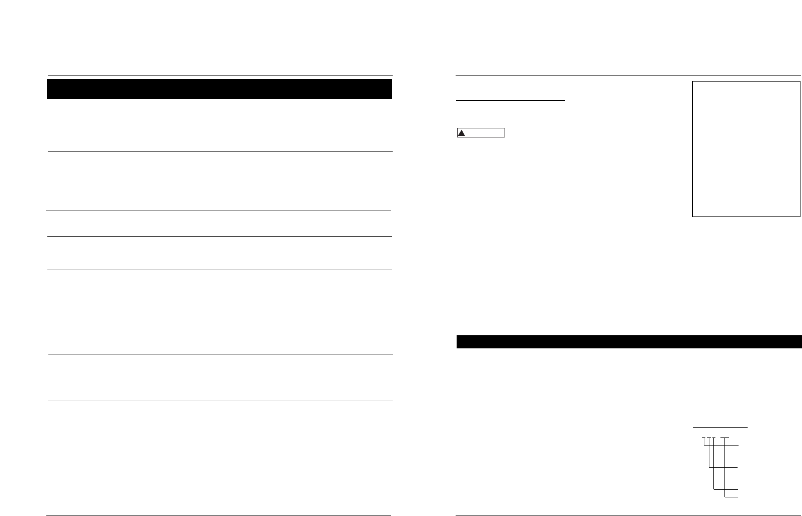
FLUX-CORED WIRE
E - 70 T- GS
Weld strength, times
10,000 pounds per
square inch
Welding positions (0
for flat or horizontal,
1 for any position)
Tubular flux-cored wire
Flux type
38 Sp
Soldadora Por Arco Con Alimentación de Cable
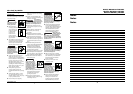
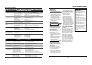
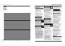
Table de Detección y Solución de Problemas - Soldadora
Síntoma Causas Posibles Medida Correctiva
1. Excedio el ciclo de trabajo
2. La pinza está mal conectada
3. El interruptor está dañado
4. El cortacircuito se activó o el
fusible está quemado
1. La boquilla de la pistola es de
un tamaño incorrecto
2. El forro de la pistola está
obstruído o dañado
3. La boquilla de la pistola está
obstruída o dañada
4. El rodillo está desgastado
5. No hay suficiente tensión
Hay escoria dentro de la boquilla
pistola
1. Hay mal contacto
2. Está usando un cordón de
extensión demasiado largo
1. El alambre está atascado
2. Se terminó el alambre
3. No hay suficiente tensión
4. El forro del alambre está
dañado
1. Espere que la soldadora se enfríe, cuando el bombillo se
apague
2. Cerciórese de que las conexiones estén bien hechas y de que la
superficie esté limpia
3. Reemplace el interruptor
4. Reduzca la carga del circuito, active el cortacircuito o
reemplace el fusible
1. Use una boquilla adecuada
2. Límpielo o reemplácelo
3. Límpiela o reemplácela
4. Reemplácelo
5. Apriete el tornillo
Cerciórese de que todas las conexiones esten bien aseguradas, y
de que la superfice este limpia.
1. Cercórese de que todas las conexiones estén bien aseguradas y
que la superficie de contacto esté limpia
2. Nunca use cordones de extensión de más de 6,10 m (20 pies)
1. Recargue el alambre (1-5 acero dulce; 5-10 aluminio)
2. Reemplace el carrete
3. Apriete los tornillos si el cable se desliza
4. Reemplace el forro
No funciona
El alambre se enrolla en la
bobina
Ocurre un arco entre la
boquilla de la pistola y la
superficie de trabajo
La pinza de trabajo y/o el
cable se calientan
El alambre no circula
(Aluminio) el alambre se
quema en el extremo de la
boquillla o (Aluminio) se
forman burbujas en el
metal o se funde
completamente
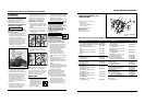
La soldadura se ampolla y
salpica
5. El fusible está quemado
(WG3060)
6. El alambre está desconectado
internamente
7. La boquilla de contacto está
obstruida
1. La velocidad de alimentación es
muy lenta
2. La velocidad de desplazamiento
es muy baja o la energía es muy
alta
1. Ajustes de velocidad del cable
2. Punta de contacto demasiado
grande
3. Polaridad conectada
incorrectamente
4. Resbala el portabobinas
5. Tanque de gas vacío
5. Reemplace el fusible en el tablero de control, dentro de la
soldadora (3,15 amp de accón retardada)
6. Llame al 1-800-746-5641 (en EUA) para recibir asistenciia
7. Reemplace la boquilla de contacto
1. Use velocidades entre 7 - 10
2. Aumente la velocidad de desplazamiento o disminuya la
energía
1. Ajuste el valor correcto
2. Remplace la punta de contacto
3. Invierta la polaridad
4. Aumente la tensión
5. Remplace el tanque de gas
7
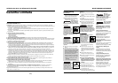
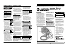
Welding Guidelines
Models WG2060 and WG2064
Supply Cable Replacement
1. Verify that welder is OFF and
power cord disconnected.
2. Remove welder side panel to
expose switches.
3. Disconnect the black power cord
wire connected to the switch
and the white cord wire from
the transformer windings.
4. Disconnect the green power
cord wire connected to welder
base.
5. Loosen the cord strain relief
screw(s) and pull cord out of
strain relief and wire post.
6. Install new cord in reverse order.
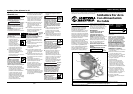
General
This welding machine can utilize the Flux
Cored Arc Welding (FCAW) process or
the Gas Metal Arc Welding (GMAW)
process. The weld must be protected
(shielded) from contaminants in the air
while it is molten. The FCAW process uses
a tubular wire with a flux material inside.
The flux creates a shielding gas when
melted. The GMAW process uses inert
gas to shield the weld while molten.
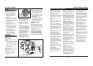
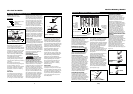
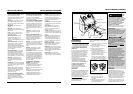
When current is produced by a
transformer (welding machine) and flows
through the circuit to the weld wire, an
arc is formed between the end of the
weld wire and the work piece. This arc
melts the wire and the work piece. The
melted metal of the weld wire flows into
the molten crater and forms a bond with
the work piece as shown (Figure 8).
Arc Welding Basics
Five basic techniques affect weld quality.
These are: wire selection, heat setting,
weld angle, wire speed, and travel
speed. An understanding of these
techniques is necessary for effective
welds.
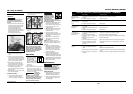
HEAT SETTING
The correct heat involves the adjustment
of the welding machine to the required
setting. Heat or voltage is regulated by a
switch on the welder. The heat setting
used depends on the size (diameter) and
type of wire, position of the weld, and
the thickness of the work piece. Consult
specifications listed on the welder. It is
suggested that the welder practice with
scrap metal to adjust settings, and
compare welds with Figure 10.
www.chpower.com
Maintenance
(Continued)
3. Inspect the condition of the gun tip
and nozzle. Remove any weld slag.
Replace gun tip or nozzle if damaged.
Do not operate this
welding machine
with cracked or missing insulation on
welding cables, wire feed gun or power
cord.
EVERY 3 MONTHS:
1. Replace any unreadable safety labels
on the welder.
2. Use compressed air to blow all dust
and lint from ventilation openings.
3. Clean wire groove on drive roller.
Remove wire from feed mechanism,
remove screws from drive roller
housing. Use a small wire brush to
clean drive roll. Replace if worn or
damaged
Consumable and Wear Parts
The following parts require routine
maintenance:
• Wire feed drive roller
• Gun liner - replace if worn
• Nozzle/contact tips
• Wire - This welder will accept either 4”
or 8” diameter spools. Flux-Cored
welding wire is susceptible to
!
WARNING
moisture and oxidizes over time, so it
is important to select a spool size that
will be used within approximately 6
months. For mild steel welding, AWS
ER70S6 solid wire or AWS E71T-GS
Flux-Cored wire is recommended.
CHANGING WIRE SIZES
This welder is setup for .035 (.9mm)
wire. If a different wire size is used, the
wire feed drive roller and contact tip
may need changing. There are two
grooves in the drive roller. The small
groove is for .024 (.6mm) wire and the
other is for .030-.035 (.8-.9mm) wire.
Remove the roller cover and flip the
drive roller to choose the correct
groove (See parts breakdown). The
contact tip should also match the wire
diameter used. The tip diameter is
marked on the contact tip in inches or
millimeters.