


Manufacturer reserves the right to discontinue, or change at any time, specifications or designs without notice and without incurring obligations.
PC 111 Catalog No. 535-034 Printed in U.S.A. Form 50TJ-17SI Pg 1 2-01 Replaces: 50TJ-14SI
Book 1
Ta b 1 b
Installation, Start-Up and
Service Instructions
CONTENTS
Page
SAFETY CONSIDERATIONS
. . . . . . . . . . . . . . . . . . . . . . . . .1
INSTALLATION
. . . . . . . . . . . . . . . . . . . . . . . . . . . . . . . . . . . 1-18
Step 1 — Provide Unit Support
. . . . . . . . . . . . . . . . . . . . . .1
• ROOF CURB
• ALTERNATE UNIT SUPPORT
Step 2 — Rig and Place Unit
. . . . . . . . . . . . . . . . . . . . . . . . .1
• POSITIONING
• ROOF MOUNT
Step 3 — Field Fabricate Ductwork
. . . . . . . . . . . . . . . . . .7
Step 4 — Make Unit Duct Connections
. . . . . . . . . . . . . . .7
Step 5 — Trap Condensate Drain
. . . . . . . . . . . . . . . . . . . .7
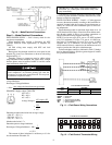
Step 6 — Make Electrical Connections
. . . . . . . . . . . . . .8
• FIELD POWER SUPPLY
• FIELD CONTROL WIRING
• OPTIONAL NON-FUSED DISCONNECT
• OPTIONAL CONVENIENCE OUTLET
Step 7 — Make Outdoor-Air Inlet
Adjustments
. . . . . . . . . . . . . . . . . . . . . . . . . . . . . . . . . . . . . . .11
• MANUAL OUTDOOR-AIR DAMPER
• OPTIONAL ECONOMI$ER
Step 8 — Install Outdoor-Air Hood
. . . . . . . . . . . . . . . . . .12
Step 9 — Install All Accessories
. . . . . . . . . . . . . . . . . . . .15
• MOTORMASTER® I CONTROL INSTALLATION
• MOTORMASTER III CONTROL INSTALLATION
Step 10 — Install Humidistat for Optional
MoistureMiser Dehumidification Package
. . . . . . . . .16
START-UP
. . . . . . . . . . . . . . . . . . . . . . . . . . . . . . . . . . . . . . . 18-24
SERVICE
. . . . . . . . . . . . . . . . . . . . . . . . . . . . . . . . . . . . . . . . 24-31
TROUBLESHOOTING
. . . . . . . . . . . . . . . . . . . . . . . . . . . . 32,33
START-UP CHECKLIST
. . . . . . . . . . . . . . . . . . . . . . . . . . CL-1
SAFETY CONSIDERATIONS
Installation and servicing air-conditioning equipment can be
hazardous due to system pressure and electrical components.
Only trained and qualified service personnel should install, re-
pair, or service air-conditioning equipment.
Untrained personnel can perform basic maintenance func-
tions of cleaning coils and filters and replacing filters. All other
operations should be performed by trained service personnel.
When working on air-conditioning equipment, observe precau-
tions in the literature, tags and labels attached to the unit, and
other safety precautions that may apply.
Follow all safety codes. Wear safety glasses and work
gloves. Use quenching cloth for unbrazing operations. Have
fire extinguishers available for all brazing operations.
INSTALLATION
Step 1 — Provide Unit Support
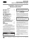
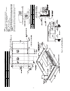
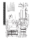
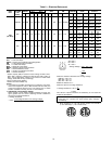
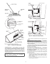
ROOF CURB — Assemble and install accessory roof curb or
horizontal adapter roof curb in accordance with instructions
shipped with the curb or horizontal adapter. Accessory roof
curb and horizontal adapter roof curb and information required
to field fabricate a roof curb or horizontal adapter roof curb are
shown in Fig. 1 and 2. Install insulation, cant strips, roofing,
and counter flashing as shown. Ductwork can be secured to
roof curb before unit is set in place.
Curb or adapter roof curb should be level. This is necessary
to permit unit drain to function properly. Unit leveling toler-
ance is
±
1
/
16
in. per linear ft in any direction. Refer to Accesso-
ry Roof Curb or Horizontal Adapter Roof Curb Installation In-
structions for additional information as required.
ALTERNATE UNIT SUPPORT — When the curb or adapter
cannot be used, support unit with sleepers using unit curb or
adapter support area. If sleepers cannot be used, support long
sides of unit with a minimum of 3 equally spaced 4-in. x 4-in.
pads on each side.
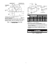
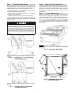
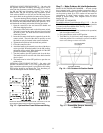
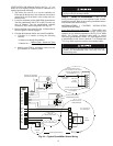
Step 2 — Rig and Place Unit —
Inspect unit for
transportation damage. File any claim with transportation
agency. Keep unit upright, and do not drop. Use spreader bars
over unit to prevent sling or cable damage. Rollers may be used
to move unit across a roof. Level by using unit frame as a refer-
ence; leveling tolerance is
±
1
/
16
in. per linear ft in any direc-
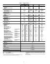
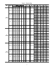
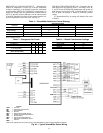
tion. See Fig. 3 for additional information. Unit weight is
shown in Table 1.
Four lifting holes are provided in ends of unit base rails as
shown in Fig. 3. Refer to rigging instructions on unit.
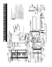
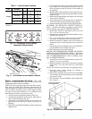
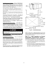
POSITIONING — Provide clearance around and above unit
for airflow, safety, and service access (Fig. 4 and 5).
Do not install unit in an indoor location. Do not locate air in-
lets near exhaust vents or other sources of contaminated air.
Although unit is weatherproof, guard against water from
higher level runoff and overhangs.
ROOF MOUNT — Check building codes for weight distribu-
tion requirements.
Before performing service or maintenance operations on
unit, turn off main power switch to unit. Electrical shock
could cause personal injury.
IMPORTANT: Units have high ambient operating lim-
its. If limits are exceeded, the unit will automatically
lock the compressor out of operation. Manual reset will
be required to restart the compressor.
IMPORTANT: The gasketing of the unit to the roof curb
or adapter roof curb is critical for a leak-proof seal.
Install gasket supplied with the roof curb or adapter roof
curb as shown in Fig. 1. Improperly applied gasket can
result in air leaks and poor unit performance.
50TJ016-028
Single-Package Rooftop Units
Electric Cooling with Electric Heat Option