


28
MOISTUREMISER SYSTEM CHARGING — The system
charge for units with the MoistureMiser option is greater than
that of the standard unit alone. The charge for units with this
option is indicated on the unit nameplate drawing. To charge
systems using the MoistureMiser Dehumidification package,
fully evacuate, recover, and re-charge the system to the name-
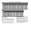
plate specified charge level. To check or adjust refrigerant
charge on systems using the MoistureMiser Dehumidification
package, charge per the standard subcooling charts. The sub-
cooler MUST be deenergized to use the charging charts. The
charts reference a liquid pressure (psig) and temperature at a
point between the condenser coil and the subcooler coil. A tap
is provided on the unit to measure liquid pressure entering the
subcooler (leaving the condenser).
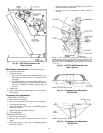
Filter Drier —
Replace whenever refrigerant system is ex-
posed to atmosphere.
Protective Devices
COMPRESSOR PROTECTION
Overcurrent
— Each compressor has internal line break motor
protection, except the circuit no. 1 on the 50TJ028 unit. Com-
pressor no. 1 on the 50TJ028 unit uses an electronic module lo-
cated with the compressor junction box, to provide motor pro-
tection. This electronic module monitors winding and dis-
charge temperatures. If these temperatures reach the trip
values, the module interrupts the control line and causes the
compressor to switch off.
Crankcase Heater
— Only the 50TJ028 unit and units with
the optional MoistureMiser Dehumidification system are
equipped with a 70-watt crankcase heater to prevent absorption
of liquid refrigerant by oil in the crankcase when the compres-
sor is idle. The crankcase heater is energized whenever there is
a main power to the unit and the compressor is not energized.
Compressor Lockout
— If any of the safeties (high-pressure,
low-pressure, freeze protection thermostat, compressor internal
thermostat) trip, or if there is loss of power to the compressors,
the CLO (compressor lockout) will lock the compressors off.
To reset, manually move the thermostat setting.
EVAPORATOR FAN MOTOR PROTECTION — A manu-
al reset, calibrated trip, magnetic circuit breaker protects
against overcurrent. Do not bypass connections or increase the
size of the breaker to correct trouble. Determine the cause and
correct it before resetting the breaker.
CONDENSER-FAN MOTOR PROTECTION — Each
condenser-fan motor is internally protected against
overtemperature.
HIGH- AND LOW-PRESSURE SWITCHES — If either
switch trips, or if the compressor overtemperature switch acti-
vates, that refrigerant circuit will be automatically locked out
by the CLO. To reset, manually move the thermostat setting.
FREEZE PROTECTION THERMOSTAT (FPT) — An FPT
is located on the top and bottom of the evaporator coil. It de-
tects frost build-up and turns off the compressor, allowing the
coil to clear. Once the frost has melted, the compressor can be
reenergized.
Relief Devices —
All units have relief devices to protect
against damage from excessive pressures (e.g., fire). These de-
vices protect the high and low side.
Control Circuit, 24-V —
This control circuit is protect-
ed against overcurrent by a 3.2-amp circuit breaker. Breaker
can be reset. If it trips, determine cause of trouble before
resetting.
Replacement Parts —
A complete list of replacement
parts may be obtained from any Carrier distributor upon
request.
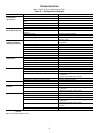
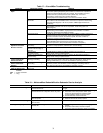
EconoMi$er LEDs —
The EconoMi$er control module
has an LED for diagnostic purposes. The flash code identifica-
tion is shown in Table 15.
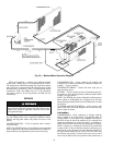
Optional Hinged Access Doors —
When the optional
service package is ordered or the if the hinged access doors
option is ordered, the unit will be provided with external and
internal hinged access doors to facilitate service.
Four external hinged access doors are provided. All external
doors are provided with 2 large
1
/
4
turn latches with folding
bail-type handles. (Compressor access doors have one latch.) A
single door is provided for filter and drive access. One door is
provided for control box access. The control box access door is
interlocked with the non-fused disconnect which must be in the
OFF position to open the door. Two doors are provided for ac-
cess to the compressor compartment.
Two internal access doors are provided inside the filter/
drive access door. The filter access door (on the left) is secured
by 2 small
1
/
4
turn latches with folding bail-type handles. This
door must be opened prior to opening the drive access door.
The drive access door is shipped with 2 sheet metal screws
holding the door closed. Upon initial opening of the door, these
screws may be removed and discarded. The door is then held
shut by the filter access door, which closes over it.
IMPORTANT: After prolonged shutdown or servicing,
energize the crankcase heaters for 24 hours before start-
ing the compressors.
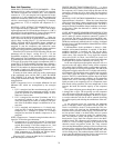
50
40
100
150
200
250
300
350
400
60
80
100
120
140
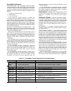
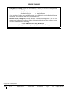
ALL OUTDOOR FANS MUST BE OPERATING
LIQUID PRESSURE AT LIQUID VALVE (PSIG)
LIQUID TEMPERATURE AT LIQUID VALVE (DEG F)
BOTH CIRCUITS
REDUCE CHARGE IF BELOW CURVE
ADD CHARGE IF ABOVE CURVE
Fig. 36 — Cooling Charging Chart