


7
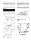
Step 3 — Field Fabricate Ductwork —
Secure all
ducts to building structure. Use flexible duct connectors be-
tween unit and ducts as required. Insulate and weatherproof all
external ductwork, joints, and roof openings with counter
flashing and mastic in accordance with applicable codes.
Ducts passing through an unconditioned space must be in-
sulated and covered with a vapor barrier.
The 50TJ units with electric heat require a 1-in. clearance
for the first 24 in. of ductwork.
Outlet grilles must not lie directly below unit discharge.
NOTE: A 90-degree elbow must be provided in the ductwork
to comply with UL (Underwriters’ Laboratories) codes for use
with electric heat.
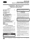
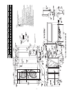
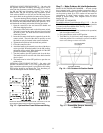
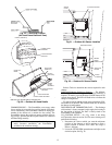
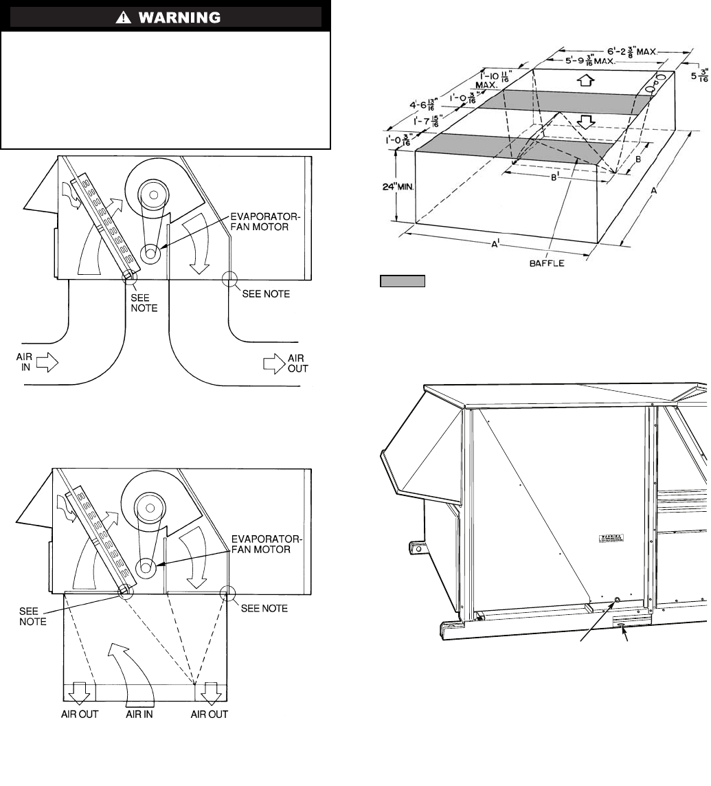
Step 4 — Make Unit Duct Connections —
Unit
is shipped for through-the-bottom duct connections. Ductwork
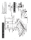
openings are shown in Fig. 6. Field-fabricated concentric duct-
work may be connected as shown in Fig. 7 and 8. Attach all
ductwork to roof curb and roof curb basepans. Refer to installa-
tion instructions shipped with accessory roof curb for more
information.
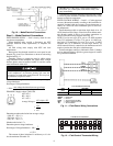
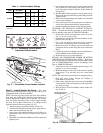
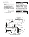
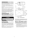
Step 5 — Trap Condensate Drain —
See Fig. 4, 5,
and 9 for drain location. Plug is provided in drain hole and
must be removed when unit is operating. One
3
/
4
-in. half-
coupling is provided inside unit evaporator section for conden-
sate drain connection. An 8
1
/
2
in. x
3
/
4
-in. diameter nipple and a
2-in. x
3
/
4
-in. diameter pipe nipple are coupled to standard
3
/
4
-in. diameter elbows to provide a straight path down through
holes in unit base rails (see Fig. 10). A trap at least 4-in. deep
must be used.
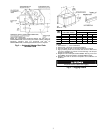
For vertical supply and return units, tools or parts could
drop into ductwork and cause an injury. Install a 90 degree
turn in the return ductwork between the unit and the condi-
tioned space. If a 90 degree elbow cannot be installed, then
a grille of sufficient strength and density should be installed
to prevent objects from falling into the conditioned space.
Due to electric heater, supply duct will require 90 degree
elbow.
NOTE: Do not drill in this area; damage to basepan may result in
water leak.
Fig. 6 — Air Distribution — Thru-the-Bottom
(50TJ020-028 Shown)
NOTE: Do not drill in this area; damage to basepan may result in
water leak.
Fig. 7 — Concentric Duct Air Distribution
(50TJ020-028 Shown)
3/4" FPT DRAIN
CONNECTION
1-3/8"
DRAIN HOLES
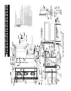
Shaded area indicates block-off panels.
NOTE: Dimensions A, A
′,
and B, B
′
are obtained from field-supplied
ceiling diffuser.
Fig. 8 — Concentric Duct Details
Fig. 9 — Condensate Drain Details
(50TJ016,020 Shown)