


27
EconoMi$er Adjustment
LED INDICATION — The EconoMi$er controller features
an onboard diagnostic LED (light-emitting diode) that flashes
to indicate its status. See Table 15 for flash codes. The control-
ler also has terminal connections (REM LED) for remotely
mounting an LED, if desired. The flash code priorities are as
follows:
1. On/Off or continuous flash
2. Critical fault
3. Non-critical fault
If any sensors are opened, shorted, or removed, the
EconoMi$er determines whether the failure is critical or non-
critical and flashes the appropriate code. If a non-critical sensor
fault occurs (i.e., outdoor air humidity), the EconoMi$er auto-
matically reconfigures its control strategy to a more appropriate
mode. If a critical sensor fault occurs (i.e., supply air sensor),
the EconoMi$er reverts to a safe mode of operation until the
sensor problem is resolved.
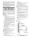
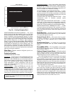
MANUAL CONFIGURATION PUSHBUTTON — The
EconoMi$er controller also features an onboard button (CON-
FIG) to help troubleshoot the system. See Fig. 16. The button
can perform 3 different functions.
Pressing the CONFIG button for more than three seconds,
but less than ten seconds and then releasing will start the auto-
matic test procedure. The damper will modulate fully open,
wait, and modulate closed. This process takes three minutes to
complete. Use this feature to determine if the actuator can be
commanded.
If the CONFIG button is pressed and held for ten seconds
and less than 30 seconds then released, the EconoMi$er con-
troller reconfigures its mode of operation based on the sensors
that are connected and functioning normally, and cancels the
automatic test procedure.
If the EconoMi$er controller recognized a non-critical
sensor fault, and flashed a code (i.e., FLASH 6, outdoor air
humidity sensor fault) the FLASH CODE will be cleared, and
normal operation begins. Ensure faulty sensor is removed
before clearing faults.
If the EconoMi$er controller recognizes a critical sensor
fault, and flashes a code (i.e., FLASH 4, discharge air thermo-
stat fault) the FLASH code will not be cleared, and the
EconoMi$er will remain in the safe operation mode. The
sensor fault must be corrected to enable EconoMi$er to revert
to normal operation.
If the CONFIG button is pressed and held for more than
30 seconds and released, the EconoMi$er controller will enable
the enthalpy comparison strategy (with outdoor air enthalpy
and return air enthalpy sensors installed).
Power Failure —
Dampers have a spring return. In event
of power failure, dampers will return to fully closed position
until power is restored.
Do not manually operate damper
motor.
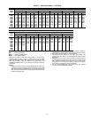
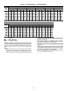
Refrigerant Charge —
Amount of refrigerant charge is
listed on unit nameplate and in Table 1. Refer to Carrier GTAC
II; Module 5; Charging, Recovery, Recycling, and Reclamation
section for charging methods and procedures. Unit panels must
be in place when unit is operating during charging procedure.
NOTE: Do not use recycled refrigerant as it may contain con-
taminants.
NO CHARGE — Use standard evacuating techniques. After
evacuating system, weigh in the specified amount of refriger-
ant (refer to Table 1).
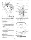
LOW CHARGE COOLING — Using cooling charging chart
(see Fig. 36), add or remove refrigerant until conditions of the
chart are met. Note that charging chart is different from those
normally used. An accurate pressure gage and temperature-
sensing device is required. Charging is accomplished by ensur-
ing the proper amount of liquid subcooling. Measure liquid line
pressure at the liquid line service valve using pressure gage.
Connect temperature sensing device to the liquid line near the
liquid line service valve and insulate it so that outdoor ambient
temperature does not affect reading.
TO USE THE COOLING CHARGING CHART — Use the
above temperature and pressure readings, and find the intersec-
tion point on the cooling charging chart. If intersection point on
chart is above line, add refrigerant. If intersection point on
chart is below line, carefully recover some of the charge. Re-
check suction pressure as charge is adjusted. NOTE: Indoor-air
CFM must be within normal operating range of unit. All out-
door fans must be operating.
The TXV (thermostatic expansion valve) is set to maintain
between 15 and 20 degrees of superheat at the compressors.
The valves are factory set and should not require re-adjustment.
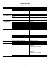
Table 15 — EconoMi$er Control Module Flash Code Identification
FLASH CODE CAUSE ACTION TAKEN BY ECONOMI$ER
Constant On
Normal operation Normal operation.
Constant Off
No power No operation.
Continuous
Flash
CONFIG button pushed and held
between 3 and 9 seconds
Outdoor air damper is stroked fully open, then closed
(automatic test procedure takes 3 minutes to complete).
Critical Fault
Flash One
Control board fault System shutdown.
Flash Two
Thermostat fault (i.e., Y2 without Y1) System shutdown until corrected.
Flash Three
Actuator fault Revert to mechanical cooling only.
Flash Four
Discharge air thermistor fault
Continue operation with damper at minimum position.
Revert to mechanical cooling only.
Flash Five
Outdoor air temperature sensor fault
Continue operation with damper at minimum position.
Disable mechanical cooling lockout.
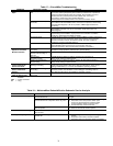
Non-Critical Fault
Flash Six
Outdoor air humidity sensor fault Continue operation with dry bulb or dry bulb differential switchover.
Flash Seven
Return air temperature sensor fault
Continue operation with single enthalpy EconoMi$er
switchover or dry bulb EconoMi$er switchover (without
humidity sensor).
Flash Eight
Return air humidity sensor fault
Continue operation with single enthalpy, differential dry
bulb, or dry bulb EconoMi$er switchover.
Flash Nine
Carbon Dioxide (CO
2
) sensor fault Continue operation without ventilation control.
Flash Ten
Onboard adjustment potentiometer fault Continue operation with default potentiometer settings.