


6
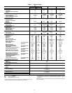
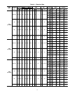
Table 1 — Physical Data
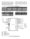
LEGEND
*Circuit 1 uses the lower portion of condenser coil and lower portion of evap-
orator coils; and Circuit 2 uses the upper portion of both coils.
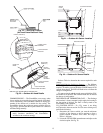
†The 50TJ028 units requires 2-in. industrial-grade filters capable of handling
face velocities of up to 625 ft/min (such as American Air Filter no. 5700 or
equivalent).
NOTE: The 50TJ016-028 units have a low-pressure switch (standard) located
on the suction side.
UNIT 50TJ
016
020 024 028
208/230, 460 v 575 v
NOMINAL CAPACITY (tons) 15 18 20 25
OPERATING WEIGHT 1550 1650 1700 1850
EconoMi$er 80
80 80 80
MoistureMiser Dehumidification
Package
40
40 40 40
COMPRESSOR/MANUFACTURER Scroll, Copeland
Quantity...Model (Ckt 1, Ckt 2)
2...ZR94KC
50, 50
2
81, 81
1...ZR108KC,
1...ZR94KC
1...ZR125KC,
1...ZR108KC
1...ZR16M3,
1...ZR125KC
Capacity Stages (%) 55, 45 55, 45 60, 40
Number of Refrigerant Circuits 22 2
Oil (oz) (Ckt 1, Ckt 2) 106, 81 106,106 136, 106
REFRIGERANT TYPE R-22
Expansion Device TXV
Operating Charge (lb-oz)
Circuit 1* 10-10
10-10
15-5 16-0 20-13
Circuit 2 12-3 13-6 13- 0
CONDENSER COIL Cross-Hatched
3
/
8
-in. Copper Tubes, Aluminum Lanced,
Aluminum Pre-Coated, or Copper Plate Fins
Rows...Fins/in. 2...17
21.7
3...15 3...15 4...15
Total Face Area (sq ft) 21.7 21.7 21.7
CONDENSER FAN Propeller Type
Nominal Cfm 10,500 10,500 14,200 14,200
Quantity...Diameter (in.) 3...22 3...22 2...30 2...30
Motor Hp...Rpm
1
/
2
...1050
1
/
2
...1050 1...1075 1...1075
Watts Input (Total) 1100 1100 3400 3400
EVAPORATOR COIL Cross-Hatched
3
/
8
-in. Copper Tubes, Aluminum Lanced or
Copper Plate Fins, Face Split
Rows...Fins/in. 2...17 3...15 3...15 4...15
Total Face Area (sq ft) 17.5 17.5 17.5 17.5
EVAPORATOR FAN Centrifugal Type
Quantity...Size (in.) 2...10 x 10 2...10 x 10 2...12 x 12 2...12 x 12 2...12 x 12
Type Drive Belt Belt Belt Belt Belt
Nominal Cfm 6000 6000 7200 8000 10,000
Motor Hp 3.7 3.0 5 7.5 10
Motor Nominal Rpm 1725 1725 1745 1745 1740
Maximum Continuous Bhp 4.25 3.45 5.90
8.7 [208/230, 575 v]
9.5 [460 v]
10.2 [208/230, 575 v]
11.8 [380, 460 v]
Motor Frame Size 56H 56H 184T 213T 215T
Nominal Rpm High/Low ——— — —
Fan r/s Range Low-Medium Static 891-1179 1159-1429 910-1095 1002-1225 1066-1283
High Static 1227-1550 — 1069-1287 1193-1458 1332-1550
Motor Bearing Type Ball Ball Ball Ball Ball
Maximum Allowable Rpm 1550 1550 1550 1550 1550
Motor Pulley Pitch Diameter Low-Medium Static 3.1/4.1 4.3/5.3 4.9/5.9 5.4/6.6 4.9/5.9
Min/Max (in.) High Static 3.7/4.7 — 4.9/5.9 5.4/6.6 4.9/5.9
Nominal Motor Shaft Diameter (in.)
7
/
8
7
/
8
1
1
/
8
1
3
/
8
1
3
/
8
Fan Pulley Pitch Diameter (in.) Low-Medium Static 6.0 6.4 9.4 9.4 8.0
High Static 5.2 — 8.0 7.9 6.4
Nominal Fan Shaft Diameter (in.) 1
3
/
16
1
3
/
16
1
7
/
16
1
7
/
16
1
7
/
16
Belt, Quantity...Type...Length (in.) Low-Medium Static 1...BX...42 1...BX...45 1...BX...50 1...BX...53 2...BX...50
High Static 1...BX...42 — 1...BX...48 1...BX...50 2...BX...47
Pulley Center Line Distance (in.) 13.5-15.5 13.5-15.5 13.3-14.8 14.6-15.4 14.6-15.4
Speed Change per Full Turn of
Movable Pulley Flange (rpm)
Low-Medium Static 48 44 37 37 36
High Static 55 — 34 44 45
Movable Pulley Maximum Full Turns
From Closed Position 666 6 6
Factory Speed 3.5 3.5 3.5 3.5 3.5
Factory Speed Setting (rpm Low-Medium Static 1035 1296 1002 1120 1182
High Static 1389 — 1178 1328 1470
Fan Shaft Diameter at Pulley (in.) 1
3
/
16
1
3
/
16
1
7
/
16
1
7
/
16
1
7
/
16
HIGH-PRESSURE SWITCH (psig)
Cutout 426
Reset (Auto) 320
LOW-PRESSURE SWITCH (psig)
Cutout 27
Reset (Auto) 44
FREEZE PROTECTION THERMOSTAT (F)
Opens 30
±
5
Closes 45
±
5
OUTDOOR-AIR INLET SCREENS Cleanable
Quantity...Size (in.) 2...20 x 25 x 1
1...20 x 20 x 1
RETURN-AIR FILTERS Throwaway†
Quantity...Size (in.) 4...20 x 20 x 2
4...16 x 20 x 2
POWER EXHAUST
1
/
2
Hp, 208/230-460 v Motor Direct Drive, Propeller-Fan (Factory-Wired for 460 v)
Bhp — Brake Horsepower
TXV — Thermostatic Expansion Valve