


24
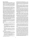
When the humidistat is satisfied, the humidistat internal
switch opens, cutting power to and deenergizing the LLSVs.
The refrigerant is routed back through the evaporators and the
sub-cooler coils are removed from the refrigerant loops. When
the thermostat is satisfied, C1 and C2 are deenergized and the
compressors, IFM, and OFMs shut off. If the thermostat
fan selector switch is in the ON position, the IFM will run
continuously.
SERVICE
Cleaning —
Inspect unit interior at beginning of each heat-
ing and cooling season and as operating conditions require.
Remove unit top panel and/or side panels for access to unit
interior.
EVAPORATOR COIL — Clean as required with a commer-
cial coil cleaner.
NOTE: The 50TJ028 unit has a mist eliminator screen attached
to the evaporator coil to prevent condensate runoff at high wet-
bulb conditions. Check periodically and clean as necessary.
CONDENSER COIL — Clean condenser coil annually and
as required by location and outdoor-air conditions. Inspect coil
monthly — clean as required.
CONDENSATE DRAIN — Check and clean each year at
start of cooling season.
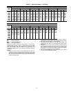
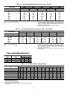
FILTERS — Clean or replace at start of each heating and cool-
ing season, or more often if operating conditions require. Refer
to Table 1 for type and size.
NOTE: The 50TJ028 unit requires industrial grade throwaway
filters capable of withstanding face velocities up to 625 fpm.
Ensure that replacement filters for the 50TJ028 units are rated
for 625 fpm.
OUTDOOR-AIR INLET SCREENS — Clean screens with
steam or hot water and a mild detergent. Do not use throwaway
filters in place of screens.
Lubrication
COMPRESSORS — Each compressor is charged with the
correct amount of oil at the factory. Conventional white oil
(Sontext 200LT) is used. White oil is compatible with 3GS oil,
and 3GS oil may be used if the addition of oil is required. See
compressor nameplate for original oil charge. A complete re-
charge should be four ounces less than the original oil charge.
When a compressor is exchanged in the field it is possible that
a major portion of the oil from the replaced compressor may
still be in the system. While this will not affect the reliability of
the replacement compressor, the extra oil will add rotor drag
and increase power usage. To remove this excess oil, an access
valve may be added to the lower portion of the suction line at
Before performing service or maintenance operations on
unit, turn off main power switch to unit. Turn off accessory
heater power switch if applicable. Electrical shock could
cause personal injury.
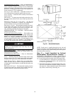
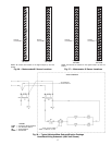
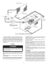
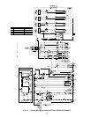
Fig. 30 — MoistureMiser Operation Diagram