


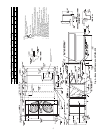

4
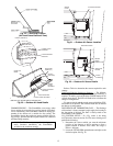
POWER EXHAUST/BAROMETRIC RELIEF
(ACCESSORY ONLY)
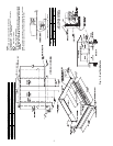
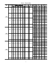
Fig. 4 — Base Unit Dimensions, 50TJ016,020
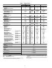
UNIT
STD UNIT
WEIGHT
ECONOMI$ER
WEIGHT
CORNER
(A)
CORNER
(B)
CORNER
(C)
CORNER
(D)
DIM A DIM B DIM C
Lb Kg Lb Kg Lb Kg Lb Kg Lb Kg Lb Kg Ft-in. mm Ft-in. mm Ft-in. mm
50TJ016
1550 703 80 36.3 391 177 365 166 384 174 410 186 3-5 1041 3-6 1067 1-10 559
50TJ020
1650 748 80 36.3 399 181 384 174 402 182 439 199 3-4 1016 3-6 1067 1- 8 508
NOTES:
1. Refer to print for roof curb accessory dimensions.
2. Dimensions in [ ] are in millimeters.
3. Center of gravity.
4. Direction of airflow.
5. Ductwork to be attached to accessory roof curb only.
6. Minimum clearance:
•
Rear: 7
′
-0
″
(2134) for coil removal. This dimension can be
reduced to 4
′
-0
″
(1219) if conditions permit coil removal from the
top.
•
Left side: 4
′
-0
″
(1219) for proper condenser coil airflow.
•
Front: 4
′
-0
″
(1219) for control box access.
•
Right side: 4
′
-0
″
(1219) for proper operation of damper and
power exhaust if so equipped.
•
Top: 6
′
-0
″
(1829) to assure proper condenser fan operation.
•
Local codees or jurisdiction may prevail.
7. With the exception of clearance for the condenser coil and the
damper/power exhaust as stated in Note #6, a removable fence or
barricade requires no clearance.
8. Dimensions are from outside of corner post. Allow 0
′
-
5
/
16
″
(8) on
each side for top cover drip edge.
9. See drawing 50TJ500352 for service option details.