


SKU 92496 PAGE 10
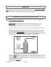
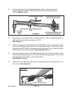
your gas supplier immediately. (See Figure F.)
7. Connect the Cutting Attachment (parts C1-C27) to the Torch Handle (parts B1-B10).
Always check the Connector (C23) and Coupling Nut (C22) for damage or oil. If
either are found, discontinue use and contact your gas supplier.
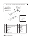
TORCH HANDLE
(PARTS B1-B10)
RED (AC) WELDING HOSE (D1B)
GREEN (OX) WELDING HOSE
(D1A)
FIGURE F
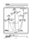
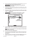
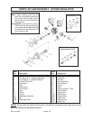
Make sure the two O-Rings (C24, C25) are not damaged or miss-
ing, otherwise gases will mix inside the Torch Handle (parts B1-
B10) and result in flashback or backfires. (See Figures G, and H.)
CUTTING ATTACHMENT (PARTS C1-C27)
O-RING
(C25)
O-RING
(C24)
CONNECTOR (C23)
COUPLING NUT (C22)
FIGURE G
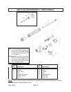
CUTTING ATTACHMENT (PARTS C1-C27)
TORCH HANDLE (PARTS B1-
B10)
FIGURE H
GREEN (OXYGEN)
WELDING HOSE
(D1A)
8. Check connections for leaks. Adjust the Acetylene Regulator (parts 1-19) and
Oxygen Regulator (parts A1-A20E) to their normal operating pressure. Use an
approved leak detection solution to check for leaks at the Welding Hoses (D1A,
and D1B) and cylinder valve connections. If leaks are found, tighten the nuts more
WARNING!
RED (ACETYLENE)
WELDING HOSE
(D1B)