


SKU 92496 PAGE 18
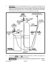
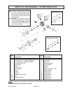
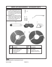
NOTE: Some parts are listed and shown for illustration purposes only, and are not avail-
able individually as replacement parts.
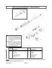
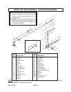
PARTS LIST AND DIAGRAM 4 - CUTTING ATTACHMENT
Note: When ordering parts from this parts list and
diagram always take the number from the No.
column (on the left) and add a suffix of C to
the beginning.
For example:
If you wished to order a Head
for this
attachment you’d take the part number from the
No. column (2) and add an C to the beginning.
So you’d order part C2.
Item Item
No Description No Description
1 Tip Nut 17 HP Spring
2 Head 18 Washer
3 Oxygen Tube 19 Valve Cap
4 Nut 20 Lever
5 Ferrule 21 Sprial Pin
6 Nut 22 Coupling Nut
7 Fuel Tube 23 Connector
8 Inner Tube (A) 24 O-Ring (Big)
9 Inner Tube (B) 25 O-Ring (Small)
10 Spiro 26 Valve Stem Assembly
11 Inner Tube (C) 26A Valve
12 O-Ring 26B Washer
13 Washer (Teflon) 26C Nut
14 Spring 26D Adjusting Knob
15 Body 27 Label (OX)
16 Valve
Components Of: #26