


SKU 92496 PAGE 16
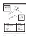
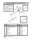
NOTE: Some parts are listed and shown for illustration purposes only, and are not avail-
able individually as replacement parts.
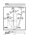
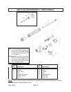
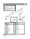
PARTS LIST AND DIAGRAM 2 - OXYGEN REGULATOR
Note: When ordering parts from this
parts list and diagram always take
the number from the No. column
(on the left) and add a suffix of A to
the beginning.
For example: If you wished to order a
Filter for this regulator you’d take
the
part number from the No.
column (6)
and add an A to the beginning. So
you’d order part A6.
Item Item
No. Description No. Description
1 Body 12C Diaphragm
2 H.P. Gauge (2.1” x 4000psi/28000kpa) 12D Centralizer
3 L.P. Gauge (2.1” x 200psi/1400kpa) 13 Slip Ring
4 Inlet Nut (CGA 540) 14 Adjusting Spring
5 Inlet Spigot 15 Spring Button
6 Filter 16 Bonnet
7 Valve Spring 17 Label
8 Anti-Vibrator 18 Adjusting Screw “T” Bar
9 Valve 19 Outlet Adaptor
10 Nozzle 20 Safety Valve
11 Plunger 20A Safety Body
12 Diaphragm Assembly 20B Safety Rubber
12A Nut 20C Safety Seat
12B Diaphragm Plate 20D Safety Spring
20E Safety Cap
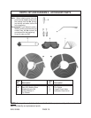
Components Of: #12
Components Of: #20