


2-10
Cisco ASR 1000 Series Aggregation Services Routers Hardware Installation and Initial Configuration Guide
OL-13208-01
Chapter 2 Cisco ASR 1000 Series Routers Components
Cisco ASR 1000 Series SPA Interface Processor
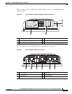
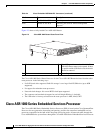
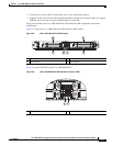
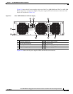
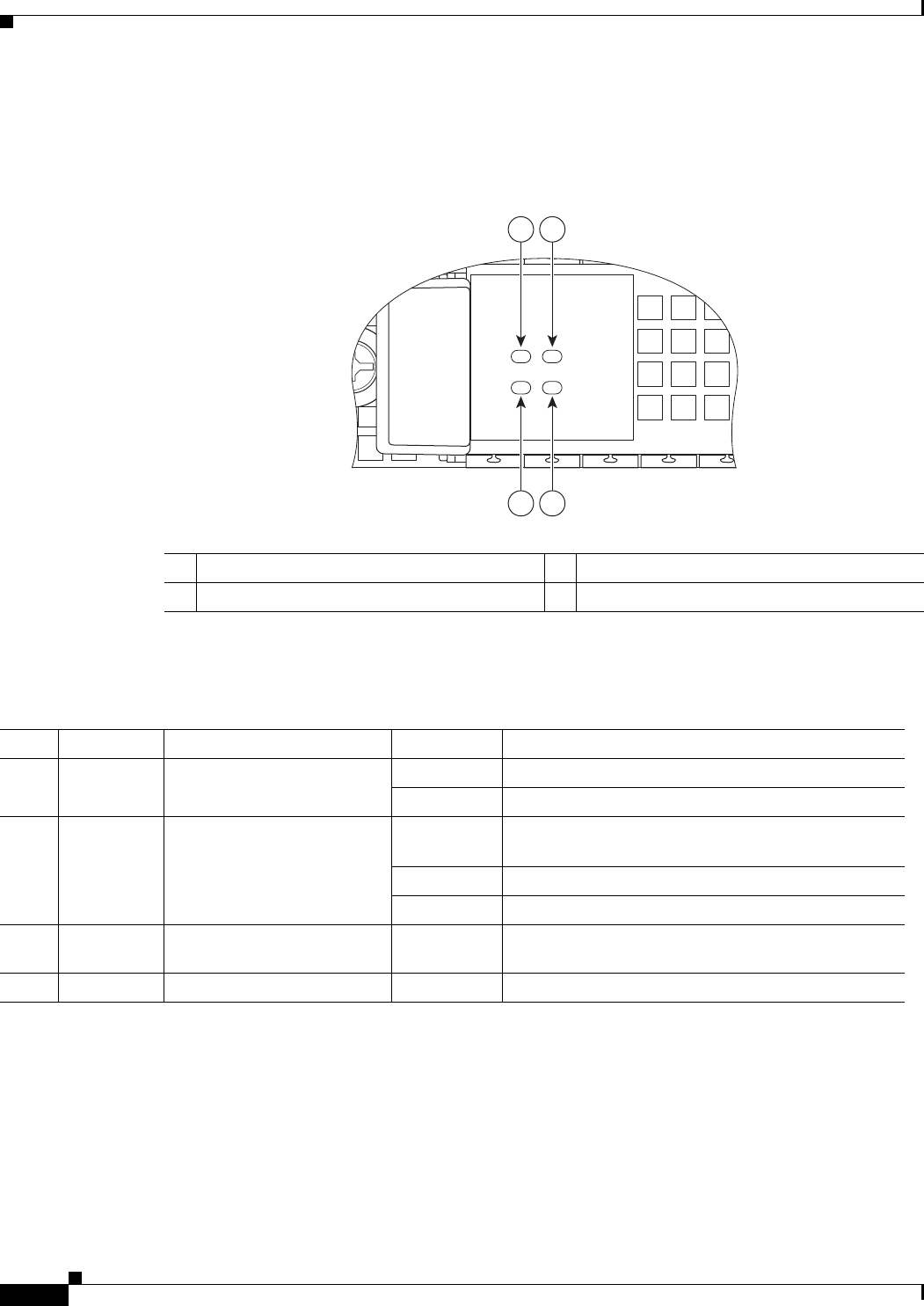
Figure 2-4 shows the Cisco ASR 1000 Series Embedded Services Processor (ESP10) LEDS on the front
panel.
Figure 2-4 Cisco ASR1000-ESP10 Faceplate LEDs
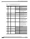
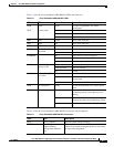
Table 2-5 lists the Cisco ASR1000-ESP5 or ASR1000-ESP10 LEDs and behaviors.
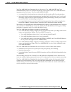
Cisco ASR 1000 Series SPA Interface Processor
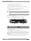
This section describes the SPA interface processor for the Cisco ASR 1006 Router, Cisco ASR 1004
Router and the Cisco ASR 1002 Router.
The Cisco ASR 1000 Series SPA Interface Processor for the Cisco ASR 1006 and Cisco ASR 1004
routers:
• Is a carrier card that inserts into a router slot like a line card.
1 Power LED 3 Status LED
2 Active LED 4 Standby LED
STBY
ACTV
STAT
ASR1000-ESP10
PWR
280080
4
3
2
1
Table 2-5 Cisco ASR1000-ESP5 or ESP-10 Processor LEDs for the Cisco ASR 1002 Router
LED Label LED Color In the Power Up State -Behavior Description
1 PWR Power Solid green All power supplies are within operational limits.
Off Off, the router is in standby mode.
3 STAT STATUS Green Code has successfully downloaded and is
operational.
Yellow BOOT ROM has successfully loaded.
Red Not booted.
2 ACTV Active Green
The embedded services processor is green when
active.
4 STBY Standby None Will always be off.