


2-24
Cisco ASR 1000 Series Aggregation Services Routers Hardware Installation and Initial Configuration Guide
OL-13208-01
Chapter 2 Cisco ASR 1000 Series Routers Components
Cisco ASR 1000 Series Router Power Supplies
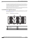
Cisco ASR Router 1004 DC Power Supply
This section provides information about the DC power supplies on the rear of the Cisco ASR 1004
Router. For the maximum branch circuit for the DC power supply module, see Table 2-7.
The DC power supply operates within specification from –48 VDC to –60 VDC continuously. The Cisco
ASR 1004 Router has two of the same type power supplies in power supply slot 0 and power supply
slot 1. The power supply slot numbers are on the left side of the chassis and the power supplies are
located on the floor of the chassis.
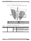
The DC power supply input connector is a terminal block style that will allow crimp type lugs accepting
up to AWG #8 wire. The terminal block is compliant to all safety agencies and electrical requirements
of the supply. The terminal block accepts two-hole lugs (#10 stud) for all connections with center to
center spacing of 0.625 inches. A plastic cover goes over the terminal block to prevent accidental
contact. The connection order shall be negative (–), positive (+), and GND terminals.
The unit requires a power switch circuit breaker to serve as the main disconnect for the DC input to the
power supply (Table 2-7 see for current rating requirements.) The power supply unit is secured into the
system chassis with four captive screws mounted on the faceplate.
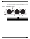
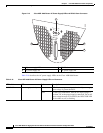
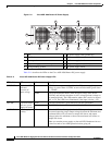
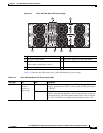
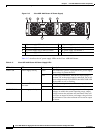
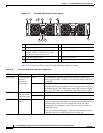
Cisco ASR 1004 Router DC Power Supply LEDs and Connector
Figure 2-14 shows the DC power supplies at the rear of the Cisco ASR 1004 Router. The Cisco
ASR 1004 Router supports up to two power supplies. The power supply LEDs and connectors on the rear
of the chassis are described in the Table 2-14.
FAN OK Bi-color LED indicates
fan status
Green LED illuminates green when all fans are operational.
Red The LED illuminates red when a fan failure is detected.
OUTPUT FAIL Power supply activity Red LED is red and turned off to signal that the AC output
voltages are within the normal operating range; output
voltage between the minimum and maximum limits will
not create an output fail alarm, and output voltages below
the minimum or above the maximum will create an output
fail alarm.
When you turn the power supply on, the red LED is
illuminated for two to three seconds for testing LED
operation before going off.
LED Label LED Color Description