


2-28
Cisco ASR 1000 Series Aggregation Services Routers Hardware Installation and Initial Configuration Guide
OL-13208-01
Chapter 2 Cisco ASR 1000 Series Routers Components
Cisco ASR 1000 Series Router Power Supplies
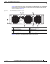
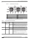
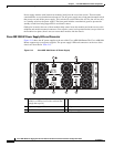
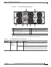
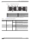
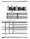
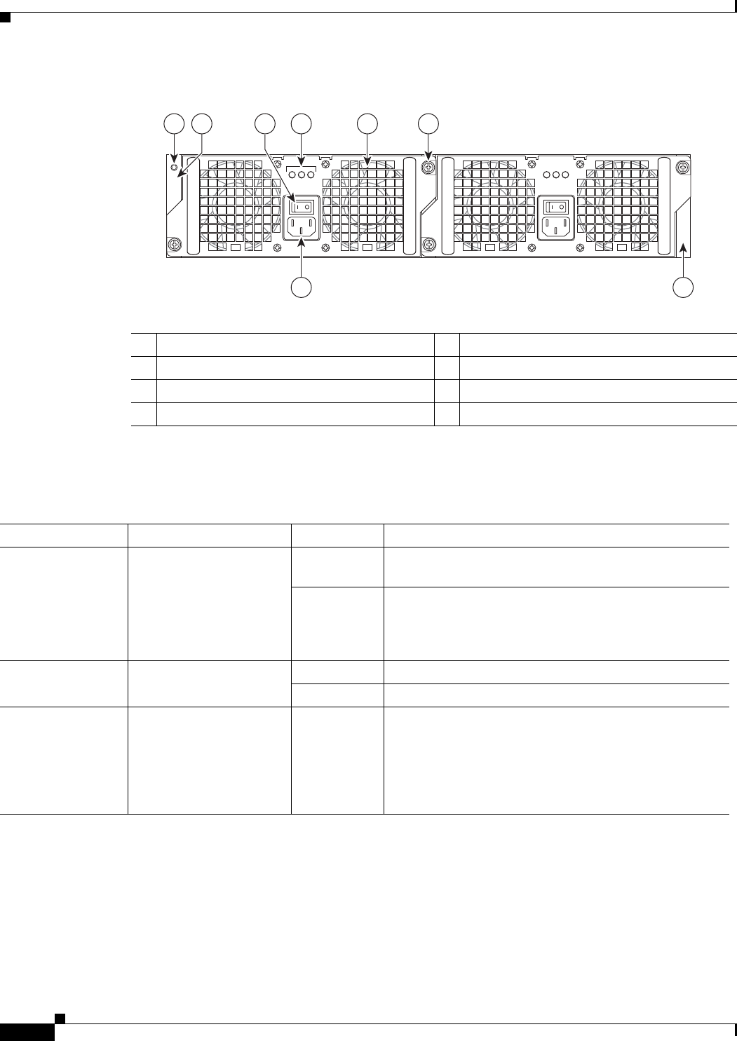
Figure 2-15 Cisco ASR 1002 Router AC Power Supply
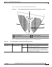
Table 2-17 describes the AC power supply LEDs on the Cisco ASR 1002 Router.
Table 2-17 Cisco ASR 1002 Router AC Power Supply LEDs
1 AC power supply ESD socket 5 AC power supply fan
2 AC power supply slot number 0 6 AC power supply captive installation screw
3 AC power supply On (I) /Off (O) switch 7 AC power supply slot number 1
4 AC power supply LEDs 8 AC power supply inlet
OUTPUTINPUT
FAIL
OK OK
FAN OUTPUTINPUT
FAIL
OK OK
FAN
This unit might have more than
one power supply connection.
All connections must be removed
to de-energize the unit.
This unit might have more than
one power supply connection.
All connections must be removed
to de-energize the unit.
0
1
8 7
280288
41 5 63
2
LED Label LED Color Description
INPUT OK Power supply activity Green LED illuminates green to signal that the AC power supply
input voltage is greater than 85V.
None If LED is not illuminated, then the AC input voltage is
less than 70V or the power supply is turned off. For an AC
input voltage between 70V and 85V, the INPUT OK LED
can be either on, off, or flashing
FAN OK Bi-color LED indicates
fan status
Green LED illuminates green when all fans are operational.
Red The LED illuminates red when a fan failure is detected.
OUTPUT FAIL Power supply activity Red LED is red and turned off to signal that the AC output
voltages are within the normal operating range; output
voltage between the minimum and maximum limits will
not create an output fail alarm, and output voltages below
the minimum or above the maximum will create an output
fail alarm.