


2-25
Cisco ASR 1000 Series Aggregation Services Routers Hardware Installation and Initial Configuration Guide
OL-13208-01
Chapter 2 Cisco ASR 1000 Series Routers Components
Cisco ASR 1000 Series Router Power Supplies
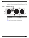
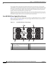
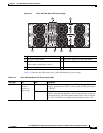
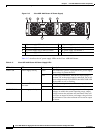
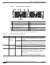
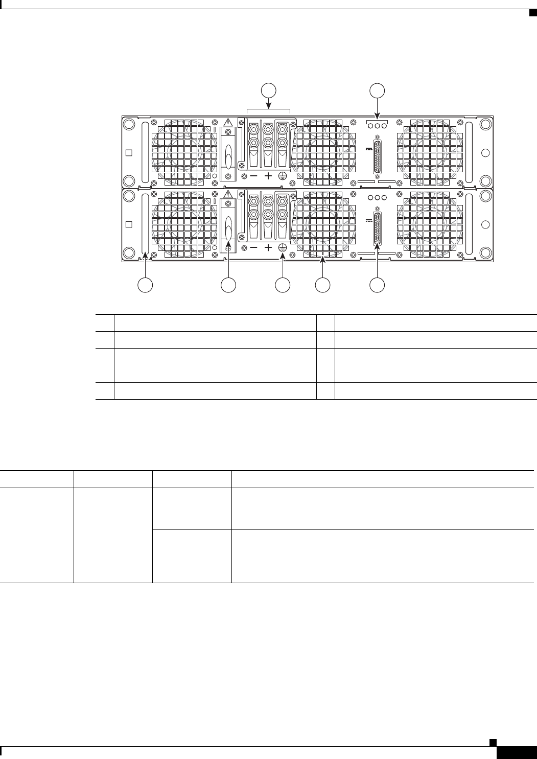
Figure 2-14 Cisco ASR 1004 Router DC Power Supply
Table 2-14 describes the LEDs on the Cisco ASR 1004 Router DC power supply.
Table 2-14 Cisco ASR 1004 Router DC Power Supply LEDs
1 DC power supply terminal and plastic cover 5 Earth grounding symbol
2 DC power supply LEDs 6 DC power supply On (|) /Off (O) switch
3 DB-25 alarm connector
Power supply ground lugs (+ and –)
7 DC power supply handle
4 DC power supply fan
280185
OUTPUT INPUT
FAIL
OK OK
FAN
60V
1A MAX
OUTPUT INPUT
FAIL
OK OK
FAN
60V
1A MAX
1
2
345
67
LED Label LED Color Description
INPUT OK A bi-color LED
indicates
presence of
input voltage
Green LED illuminates green to signal that the DC power supply input
voltage is greater than–43.5VDC at turn-on and remains green down
to –39VDC.
Amber The LED illuminates amber when the input voltage (falls below
–39VDC) and indicates that there is still a voltage present (voltage on
the terminal block). The LED remains amber and is active to around
20V +/-5V. The LED is not illuminated if the input is below –15V.