


2-22
Cisco ASR 1000 Series Aggregation Services Routers Hardware Installation and Initial Configuration Guide
OL-13208-01
Chapter 2 Cisco ASR 1000 Series Routers Components
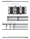
Cisco ASR 1000 Series Router Power Supplies
Power supply modules with internal fan modules install into the rear of the chassis. These modules
contain handles to ease installation and removal. The AC power supply has a front panel mounted switch
that powers on and off the power supply. This switch will not disconnect the AC line, but will act only
as a standby switch to the power supply. The front panel includes a mechanical guard to prevent the
standby switch from being tripped due to accidental contact.
Guide pins located at the rear of these modules help center locate the modules and reduce stress to the
midplane and module mounted connectors. Four captive screws (tool operated latches) are provided on
the modules face plate (chassis rear) to secure these modules into the chassis.
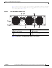
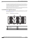
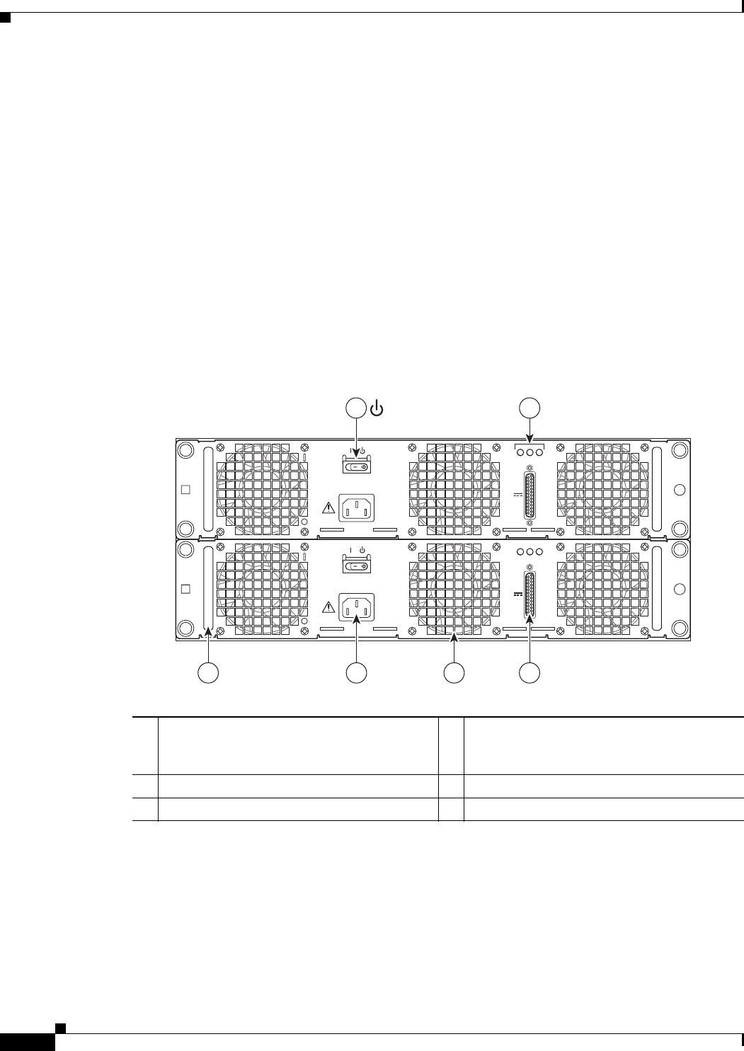
Cisco ASR 1004 AC Power Supply LEDs and Connector
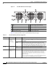
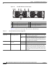
Figure 2-12 shows the AC power supplies at the rear of the Cisco ASR 1004 Router.The Cisco ASR 1004
Router supports up to two power supplies. The power supply LEDs and connectors on the rear of the
chassis are described in Table 2-13.
Figure 2-12 Cisco ASR 1004 Router AC Power Supply
1 AC power supply Standby switch (standby
symbol is a broken circle with a vertical line
through the top of it)
4 AC power supply fan
2 AC power supply LEDs 5 AC power inlet
3 DB-25 alarm connector 6 AC power supply handle
280184
OUTPUT INPUT
FAIL
OK OK
FAN
100V-240V~ 12A-5A
50-60Hz
ALARMS
60V
1A MAX
OUTPUT INPUT
FAIL
OK OK
FAN
100V-240V~ 12A-5A
50-60Hz
ALARMS
60V
1A MAX
1 2
34
6
5