


2-23
Cisco ASR 1000 Series Aggregation Services Routers Hardware Installation and Initial Configuration Guide
OL-13208-01
Chapter 2 Cisco ASR 1000 Series Routers Components
Cisco ASR 1000 Series Router Power Supplies
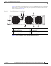
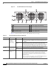
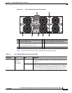
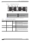
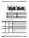
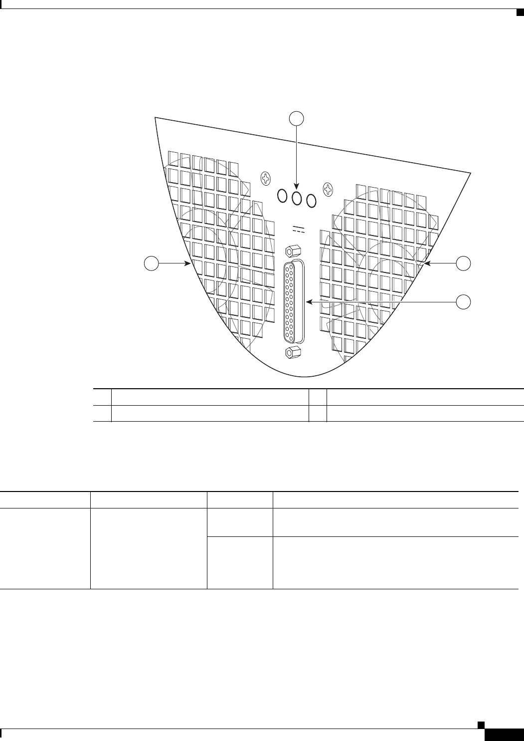
Figure 2-13 shows the AC power supplies LEDs and DB connector.
Figure 2-13 Cisco ASR 1004 Router AC Power Supply LEDs and DB -25 Alarm Connector
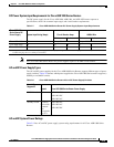
Table 2-13 describes the AC power supply LEDs on the Cisco ASR 1004 Router.
Table 2-13 Cisco ASR 1004 Router AC Power Supply LEDs and Connector
1 AC power supply LEDs 3 DB-25 alarm connector
2 Power supply fan 4 AC power supply fan
1A MAX.
OUTPUT INPUT FAN
FAIL OK OK
ALARMS
60V
280028
1
24
3
LED Label LED Color Description
INPUT OK Power supply activity Green LED illuminates green to signal that the AC power supply
input voltage is greater than 85V.
None If LED is not illuminated, then the AC input voltage is
less than 70V or the power supply is turned off. For an AC
input voltage between 70V and 85V, the INPUT OK LED
can be either on, off, or flashing