


2-17
Cisco ASR 1000 Series Aggregation Services Routers Hardware Installation and Initial Configuration Guide
OL-13208-01
Chapter 2 Cisco ASR 1000 Series Routers Components
Cisco ASR 1000 Series Router Power Supplies
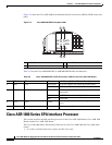
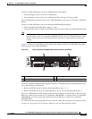
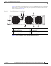
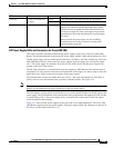
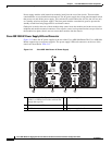
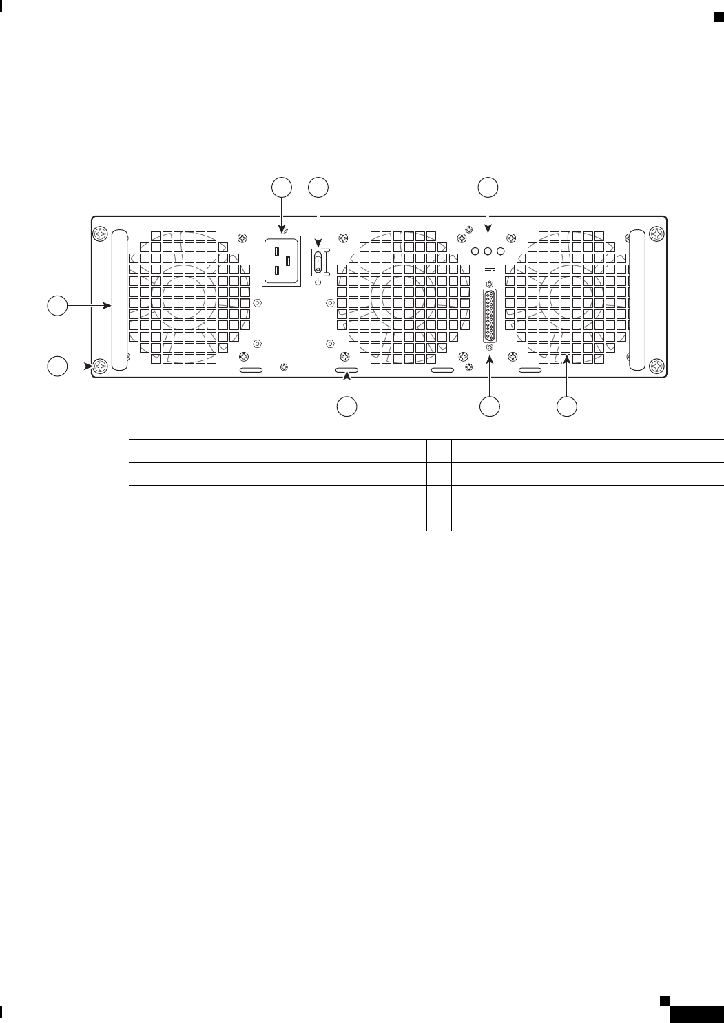
Figure 2-9 shows the AC power supplies at the rear of the Cisco ASR 1006 Router.The Cisco ASR 1006
Router supports up to two power supplies. The power supply LEDs and connectors on the rear of the
chassis are described in Table 2-10.
Figure 2-9 Cisco ASR 1006 Router AC Power Supply
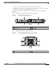
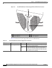
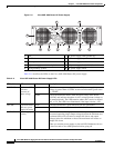
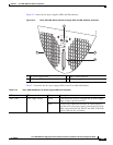
Figure 2-10 shows the AC power supplies LEDs and DB-25 alarm connector.
1 AC power supply fan 5 AC power supply handle
2 DB-25 alarm connector 6 AC power inlet
3 Tie-wrap tab 7 AC power supply Standby switch
4 AC power supply captive screw 8 AC power supply LEDs
280029
OUTPUTINPUT INPUT
FAIL OK OK
ALARMS
60V
1A MAX
100-240V~ 16-7A
50-60HZ
This unit might have more than
one power supply connection.
All connections must be removed
to de-energize the unit.
2 13
4
5
6 7
8