


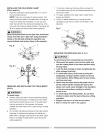
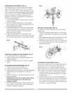
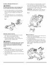
MITER ANGLE ADJUSTMENT (FIG. O)
The sliding compound miter saw scale can be easily
read, showing miter angles from 0° to 45° to the left,
and 0_'to 45 ° to the right. The miter saw table has nine
of the most common angle setttings with positive stops
at 0_',15°, 22.5 °, 31.6 °, and 45°. These positive stops
position the blade at the desired angle quickly and
accurately. Follow the process below for quickest and
most accurate adjustments.
I. Unlock the miter table by turning the miter handle (1)
counterclockwise.
2. Move the turntable while lifting up on the positive
stop locking lever (2) to align the indicator (3) to the
desired degree measurement.
3. If the desired angle is one of the nine positive stops,
release the positive stop locking lever; making sure
the lever snaps into position, and then secure by
tightening the miter handle.
4. If the miter angle desired is not one of the nine
positive stops, simply lock the miter table into position
by turning the miter handle in the clockwise direction.
Fig. 0
MITER SCALE INDICATOR ADJUSTMENT (FIG. O)
I. Move the table to the 0° positive stop.
2. Loosen the screw (4) that holds the indicator with a
Phillips screwdriver.
3. Adjust the indicator (3) to the 0° mark and retighten
screw.
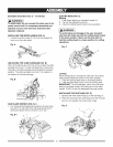
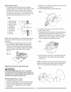
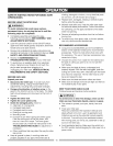
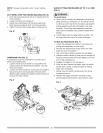
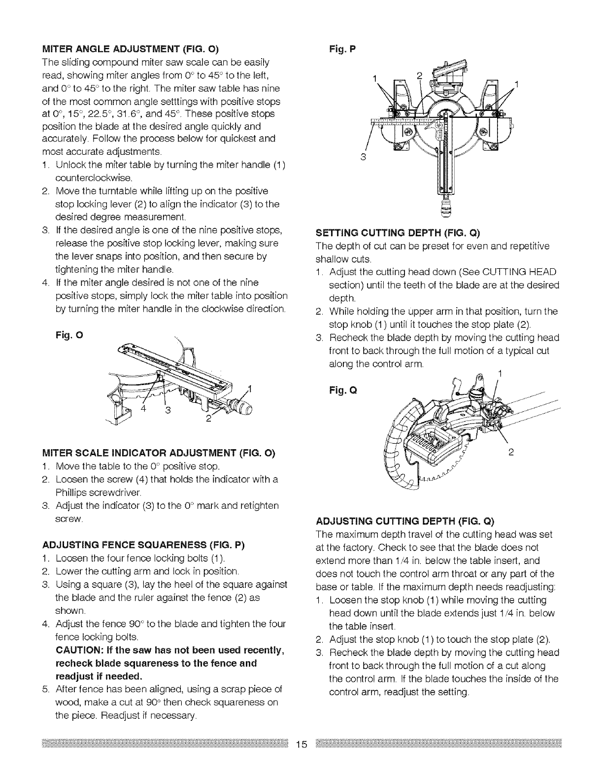
ADJUSTING FENCE SQUARENESS (FIG. P)
1. Loosen the four fence locking bolts (1).
2. Lower the cutting arm and lock in position.
3. Using a square (3), lay the heel of the square against
the blade and the ruler against the fence (2) as
shown.
4. Adjust the fence 90° to the blade and tighten the four
fence locking bolts.
CAUTION: If the saw has not been used recently,
recheck blade squareness to the fence and
readjust if needed.
5. After fence has been aligned, using a scrap piece of
wood, make a cut at 90° then check squareness on
the piece. Readjust if necessary.
Fig. P
1
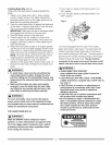
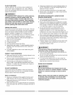
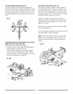
SETTING CUTTING DEPTH (FIG. Q)
The depth of cut can be preset for even and repetitive
shallow cuts.
1. Adjust the cutting head down (See CUTTING HEAD
section) until the teeth of the blade are at the desired
depth.
2. While holding the upper arm in that position, turn the
stop knob (1) until it touches the stop plate (2).
3. Recheck the blade depth by moving the cutting head
front to back through the full motion of a typical cut
along the control arm.
1
Fig. Q
2
ADJUSTING CUTTING DEPTH (FIG. Q)
The maximum depth travel of the cutting head was set
at the factory. Check to see that the blade does not
extend more than 1/4 in. below the table insert, and
does not touch the control arm throat or any part of the
base or table. If the maximum depth needs readjusting:
I. Loosen the stop knob (1) while moving the cutting
head down until the blade extends just 1/4 in. below
the table insert.
2. Adjust the stop knob (1) to touch the stop plate (2).
3. Recheck the blade depth by moving the cutting head
front to back through the full motion of a cut along
the control arm. If the blade touches the inside of the
control arm, readjust the setting.
15