


Rip Fence Dimensions:
Rip fence ..................................... 31¼"
Rip fence rails (front and rear) ..................... 56_"
Blade capacity maximum .......................... 10"
Blade arbor ..................................... %"
Dado blade capacity maximum ..................... ,¾g'
Saw Constructions:
Cabinet .................... Totallyenclosedsteel panel
Table ..................................... Cast iron
Ripfence ............................. Aluminum tube
Drive system.................................. V-belt
Exhaust port ................................ 4" Male
Miter gauge .............. Cast ironwithT-slotroller guide
Blade guard .............. Acrylic withanti-kickback pawls
Switch ............... Lockingpaddleswitch withoverload
Arbor R.RM......................... 3450 RPM approx.
Motor:................. I_HP, 3550 RPM, capacitorstart,
capacitorrun, 120/240V, 15/7.5A,
single-phase, ball bearing
Gross weight with motor ....................... 308 lbs
WARNING: Disconnect power before attempting any of the
following procedures. Be certain switch is in OFF position and
safety disconnect (or breaker) is in OFF or open position. Saw
blade must not be moving. Saw blade will rotate freely after
motor is turned off. Allow blade to come to a complete stop
before attempting any of the following procedures.
WARNING: The operation of any power tool can result in
foreign objects being thrown into the eyes, which can result in
severe eye damage. Aiways wear safety goggles complying
with United States ANSI Z87.1 before commencing power tool
operation.
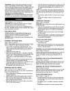
STARTING AND STOPPING THE SAW
Refer to Figure 11, page 22.
WARNING: Neveroperatesaw withoutblade guardsin
place.Be sure blade is not in contactwithworkpiecewhen
motor isstarted.Start motorand allow saw to cometofull
speed.
WARNING: Make sure the electricalcharacteristicsof motor
nameplateand powersource are the same.
• The ON/OFF switch islocatedunderthe front railofthe
tablesaw at the leftside.
• To turnsaw on, stand to eitherside of the bladewnever in
line with it.Pull up switch (Key No. 2).Always allowsaw
blade tocome uptofult speedbeforecutting.
• Do notturnmotor switch ON and OFF rapidly.This action
overheatsthe motorand may causesaw blade to loosen.
° Never leavesawwhile the poweris on.
• Toturnthe table saw off,pressthe largered OFF paddle
(KeyNo. I). Neverleave saw until cuttingtoolhas come to
a completestop.
WARNING: Foryour ownsafety, lowerblade orcuttingtool
below tablesurface. If blade istilted,return it toverticalposi-
tion.Turnoffsafety disconnector circuitbreakerwhensaw is
not in use.
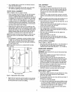
BLADE HEIGHT ADJUSTMENT
Refer to Figure 13, page 26.
* Blade height is controlled by handwheel (Key No. 30) on
the front of the saw.
• To adjust height, loosen locking hand knob (Key No. 27).
Rotate knob counterclockwise approximately three turns.
Turn handwheel to desired blade height.
CAUTION: For safety, blade should be raised only %" above
the surface of the material to be cut. However, if hollow
ground blades are used, raise blade to its maximum height to
allow for greater blade clearance.
• Lock blade height into position. Lock handwhee] (Key No.
30) by tightening locking knob (Key No. 27) clockwise.
Tighten only until snug.
IMPORTANT: Do not over tighten. Only a small amount of
pressure is necessary to lock handwheel securely.
BLADE TILT ADJUSTMENT
Referto Figure 13, page 26.
° The saw blade can be set at any angle between 90° and
45°. Blade tiltiscontrolledby the handwheel (Key No.30)
on therightside of the saw.The indicator (Key No. 86) on
front of sawshowsthe tiltangle of the blade.
• To adjusttilt, loosenlockinghandknob(Key No.27).
Rotateknob counterclockwiseat leastthreeturns.Turn
handwhee]to desiredblade angle.Lockblade angle into
position.
° Lockhandwhee](Key No.30) by tighteninglockinghand
knob (Key No.27) clockwise.Tightenonly untilsnug.
° The saw is equipped withpositivestops at 90° and 45°.
These positivestopsallow operatortopositionsaw blade
at 90° and 45° quickly and accurately.
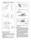
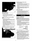
90 ° STOP ADJUSTMENT
Referto Figures 11 and 13, pages 22 and 26.
° Raise saw blade above tableas far as possible.Set blade
at 90° totable by turningthe tiltinghandwheel.Placea
square ontable and checkto see if blade is perpendicular
to the table.When checkingputsquare flush against saw
blade.Do notputsquare on teethof saw blade.
• If the bladewill nottiltto90°, turn (counterclockwise)the
set screw(Fig. 11, Key No. 44) at theleft front of the table
insert untilthe blade can be positionedto 90°.
° Once the bladehas been tiltedto 90° (confirm this using
yoursquare), tightenthe bevelhandwheellockknob,
locatedonthe side of the cabinet.This willkeep the blade
fromtiltingfurther.
° Turntheset screw (clockwise)until it comes in contact
withthe positivestop.
• Check tiltindicatorpointer,if necessary, adjust pointerso it
points to 0° mark on scale.To adjustpointer,remove
handwheeland loosenscrew(Fig. 13, Key No.84).
Be sure to tightenscrew securely after adjustmentis
completed.
45° STOP ADJUSTMENT
Refer to Figure I1, page 22.
• Tiltthesaw bladeto 45°. Usinga combinationsquare,
checkto see ifblade is 45° to the table.
° If the bladewillnottiltto45°, turn (counterclockwise)the
set screw (KeyNo. 44) locatedat the rightofthe table
insert,untiltheblade can be positioned to 45°.
10