


• Use a straight edge to check level and flatness between
main and extension tables.
• After tables are adjusted level and flat, secure the exten-
sion tables by tightening the hex nuts completely.
CHECK TABLE ALIGNMENT
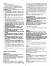
Refer to Figures 3 and 13, pages 7 and 26.
• Saws are shipped from the factory with the table adjusted
so the miter gauge slots are parallel to the saw blade.
However, in order to obtain the best results from the saw, it
is suggested this adjustment be checked before operating.
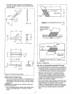
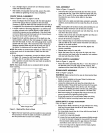
° A simple method of checking alignment is as follows: Bolt
or clamp a dowel rod or similar object to miter gauge (a
combination square can be substituted). Pick out a tooth
on front of blade and set the dowel to it so it is just touch-
ing. Move same tooth to back of blade.
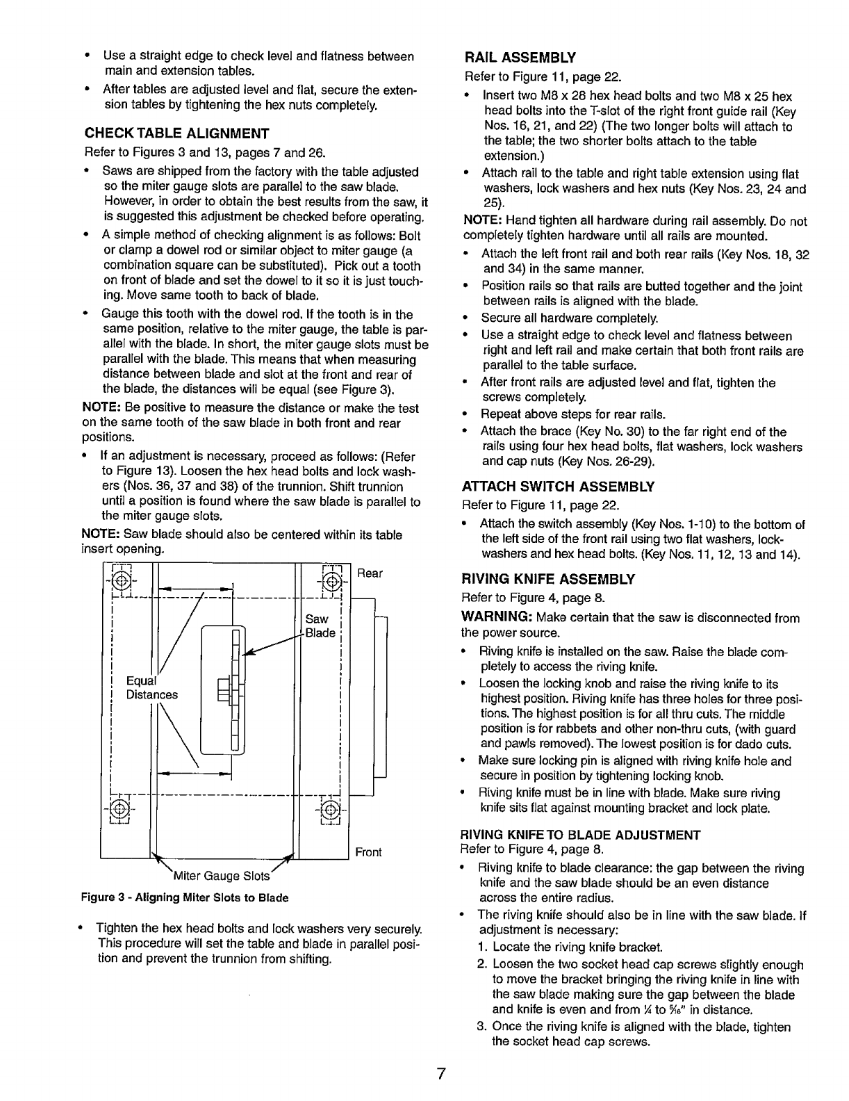
• Gauge this tooth with the dowel rod. If the tooth is in the
same position, relative to the miter gauge, the table is par-
allel with the blade. In short, the miter gauge slots must be
parallel with the blade. This means that when measuring
distance between blade and slot at the front and rear of
the blade, the distances will be equal (see Figure 3).
NOTE: Be positive to measure the distance or make the test
on the same tooth of the saw blade in both front and rear
positions.
• If an adjustment is necessary, proceed as follows: (Refer
to Figure 13). Loosen the hex head bolts and lock wash-
ers (Nos. 36, 37 and 38) of the trunnion. Shift trunnion
until a position is found where the saw blade is parallel to
the miter gauge slots.
NOTE: Saw blade should also be centered within its table
insert opening.
, r_Y
__'1",j_,
"'Miter Gauge Slots ''f
Figure 3 - Aligning Miter Slots to Blade
_aw :
_Blade :
t
I
1
I
i
I
i
I
i
I
i
1
1
I
i
I
i
Rear
Front
° Tighten the hex head bolts and lock washers very securely.
This procedure will set the table and blade in parallel posi-
tion and prevent the trunnion from shifting.
RAIL ASSEMBLY
Refer to Figure 11, page 22.
° Insert two M8 x 28 hex head bolts and two M8 x 25 hex
head bolts into the T-slot of the right front guide rail (Key
Nos. 16, 21, and 22) (The two longer bolts will attach to
the table; the two shorter bolts attach to the table
extension.)
• Attach rail to the table and right table extension using flat
washers, lock washers and hex nuts (Key Nos. 23, 24 and
25).
NOTE: Hand tighten all hardware during rail assembly. Do not
completely tighten hardware until all rails are mounted.
• Attach the left front rail and both rear rails (Key Nos. 18, 32
and 34) in the same manner.
• Position rails so that rails are butted together and the joint
between rails is aligned with the blade.
• Secure all hardware completely.
• Use a straight edge to check level and flatness between
right and left rail and make certain that both front rails are
parallel to the table surface.
• After front rails are adjusted level and flat, tighten the
screws completely.
• Repeat above steps for rear rails.
• Attach the brace (Key No. 30) to the far right end of the
rails using four hex head bolts, flat washers, lock washers
and cap nuts (Key Nos. 26-29).
ATTACH SWITCH ASSEMBLY
Refer to Figure 11, page 22.
• Attach the switch assembly (Key Nos. 1-10) to the bottom of
the left side of the front rail using two flat washers, lock-
washers and hex head bolts. (Key Nos. 11, 12, 13 and 14).
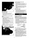
RIVING KNIFE ASSEMBLY
Refer to Figure 4, page 8.
WARNING: Make certain that the saw is disconnected from
the power source.
• Riving knife is installed on the saw. Raise the blade com-
pletely to access the riving knife.
• Loosen the locking knob and raise the riving knife to its
highest position. Riving knife has three holes for three posi-
tions. The highest position is for all thru cuts. The middle
position is for rabbets and other non-thru cuts, (with guard
and pawls removed). The lowest position is for dado cuts.
• Make sure locking pin is aligned with riving knife hole and
secure in position by tightening locking knob.
• Riving knife must be in line with blade. Make sure riving
knife sits flat against mounting bracket and lock plate.
RIVING KNIFETO BLADE ADJUSTMENT
Refer to Figure 4, page 8.
• Riving knifeto blade cJearance:thegap betweenthe riving
knife and thesaw blade should be an even distance
across the entireradius.
• The rivingknifeshouldalso be in line withthesaw blade, if
adjustmentis necessary:
1. Locatethe riving knife bracket.
2. Loosenthe two sockethead capscrews slightlyenough
to move thebracketbringing the rivingknifein linewith
the saw blade makingsure the gap betweentheblade
and knifeiseven and from¼to _," in distance,
3. Once the riving knife isalignedwiththe blade, tighten
the socket headcap screws.
7