


IMPORTANT: Table is coated with a protectant. To ensure
proper fit and operation, remove coating. Coating is easily
removed with mild solvents, such as mineral spirits, and a soft
cloth. Avoid getting solution on paint or any of the rubber or
plastic parts. Solvents may deteriorate these finishes. Use
soap and water on paint, plastic or rubber components. After
cleaning, cover all exposed surfaces with a light coating of oil.
Paste wax is recommended for table top.
WARNING: Never use highly volatile solvents. Non flamma-
ble solvents are recommended to avoid possible fire hazard.
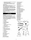
Refer to Figures 3, 4, 5, 7, 8, 9 and 10.
CAUTION: Do not attempt assembly if parts are missing.
Use this manual to order replacement parts.
Be certain all parts are clean and free of shipping preserva-
tive. Also, completely remove all parts of packing. Saw cabinet
should be directly on the floor.
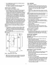
SAW INSTALLATION
Positioning the saw on a level surface (shimming may be
required) will improve stability and accuracy and prevent
warpage and failure of cast components and welds.
WARNING; Make certain that the saw is disconnected from
the power source.
ASSEMBLE THE MOBILE BASE
Refer to Figure 12, page 24.
NOTE: Finger tighten bolts and nuts until assembly of mobile
base is complete. Then tighten all fasteners securely.
• Use two M8 x 16 socket pan head bolts (Key No. 1) to
attach a corner support bracket (Key No. 3) to each fixed
support (Key Nos. 9 and 29) at the ends of one of the
caster sets.
• Repeat for the other caster set.
° Attach the front panel (Key No. 8 - stamped 'A') between
the two corner supports attached to one of the caster sets
using six M6 x I2 socket pan head bolts (Key No. 2).
Note: Place the panel edges INSIDE the corner support
surfaces.
• Attach the rear panel (Key No. 8) between the two corner
supports attached to the remaining caster set.
= Attach the left side panel (Key No. 25 - stamped 'B') to the
assemblies made in the previous two steps.
• Attach the right side panel (Key No. 33 - stamped 'C') to
the assembly made in the previous step.
ASSEMBLE BASE TO CABINET
Refer to Figures i0 and 12, pages 20 and 24.
NOTE: Saw cabinet and base are very heavy. Two people are
required to assemble this saw.
° Place a large sheet of cardboard or carpet on the floor to
protect the table top.
• Carefully place the saw cabinet upside down on the floor.
° Remove the six bolts and the back panel (Fig. 10, Key
Nos. 2 and 24). This will allow you to adjust the cabinet
holes to align with the base holes.
° Place the dust chute (Fig. 12, Key No. 30) on the cabinet
with the chute facing upwards.
° Place the mobile base assembly onto the cabinet and dust
chute and secure in position with four socket head bolts,
lock washers and flat washers (Fig. 12, Key Nos. 10, 11
and 12).
NOTE: The foot pedals of the caster sets face towards front
and rear of cabinet, the push stick is attached to the left side
of the base and rip fence hooks are on the right side of the
base.
• Press the four rubber feet (Fig. 12, Key No. 4) to the base
legs.
° Turn the saw upright, reattach the back panel of the
cabinet.
HANDWHEEL ASSEMBLY
Refer to Figure 13, page 26.
WARNING: Make certain that the saw is disconnected from
the power source.
• Place one of the handwheels (Key No. 30) onto the blade
raise/lower shaft (Key No. 56) located on the front of the
cabinet. Align the groove in the back of the handwheel
with the pin.
° Thread the locking knob (Key No. 27) onto the threaded
end of the shaft.
° Repeat the steps above to assemble the remaining hand-
wheel and locking knob onto the bevel shaft located on
the right side of the cabinet.
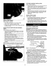
ATTACH LINE CORD HOOKS
Refer to Figure 10, page 20.
° Tilt the tableto 45°.
° Install the linecord hooks(Key No. 9) usingsockethead
bolts, washersand nuts(Key Nos. 10, 12 and 13) to the
leftside ofthe saw cabinet.
ASSEMBLE BLADE GUARD STORAGE BRACKETS
Referto Figure 12, page 24.
Installthe blade guardstorage brackets (KeyNos. 18 and 19)
to the leftside pane[ (KeyNo. 25) ofthe base usingfour
screws, lock washers and fiat washers(Key Nos.15, 16
and 17).
ASSEMBLE PUSH STICK STORAGE BRACKETS
Refer to Figure 12, page 24.
Installthe pushstickstorage brackets (KeyNo. 23) to the left
side panel(Key No. 25) of the base usingfour screws, lock
washersandflat washers(KeyNos. 20, 2t and 22).
ASSEMBLE RIP FENCE STORAGE BRACKETS
Refer to Figure 12, page 24.
Install the rip fence storage brackets (Key No. 34) to the right
side panel (Key No. 33) of the base using two screws, flat
washers and hex nuts (Key Nos. 14, 31 and 32).
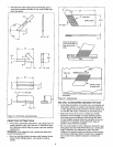
ATTACH EXTENSION TABLES
Refer to Figure 11, page 22.
° Assemble extension table (Key No. 35) to the table using
hex head bolts, lock washers and fiat washers (Key Nos.
36, 37 and 38).
° Hand tighten only. Do not tighten completely until tables
are level.
° Repeat above procedure for the other extension table.
6