


• With the blade at 45 °, tighten the bevel handwheel lock
knob to keep the blade from further tilting.
• Turn the set screw clockwise until it comes in contact with
the positive stop.
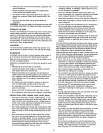
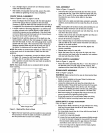
TABLE INSERT ADJUSTMENT
Refer to Figure i1, page 22.
° The table insert (Key No. 41) must always be level with the
saw table.
• Place a straight edge across the front and rear of the table
insert. Check that the insert is perfectly level with the saw
table.
° To level the table insert, turn one or more adjusting set
screws (Key No. 42) as needed and recheck.
• The table insert is equipped with a finger hold for easy
removal.
MITER GAUGE ADJUSTMENT
• Miter gauge supplied with saw is equipped with individually
adjustable index stops at 0° and 45 °, right and left, and
can be manually adjusted up to 60° right and left.
Adjustment to index stops can be made by loosening lock-
ing nut and tightening or loosening three adjusting screws.
Be sure to tighten locking nut after adjustment is made.
• Face of miter gauge has two holes for purpose of attach-
ing auxiliary facing.
• Miter gauge is accurately constructed for precision work.
Miter gauge is guided through T-slot with a roller guide
mounted at front of guide bar. Roger guide adds to miter
gauge's stability and prevents the guide bar from leaving
T-slot.
To operate miter gauge, simply loosen lock handle and
move miter gauge to desired angle. The miter gauge will
stop at 0° and 45°, both right and left. To position miter
gauge past these points, simply pull out gauge stop.
Position miter gauge at desired angle and tighten lock
handle.
• Be positive the edge of workpiece next to face of miter
gauge is straight and tight against miter gauge so that the
workpiece does not rock or rotate. Always use both hands
when operating the miter gauge.
° The miter gauge is used for cross-cutting, compound miter
cutting, miter cutting, rabbeting, bevel cutting and dadoing.
RIP FENCE ADJUSTMENT
Refer to Figure 9, page 18.
The saw's rip fence isprecisionmanufactured, incorporating
fine adjustmentsfor accuratecuts.The sawis built toallow
the operatorto accuratelyadjustthe rip fence withoutprob-
lems ina matter of seconds.
LEVELING THE FENCE TO THE TABLE
Refer to Figure 9, page 18.
• Liftthe lockhandle (Key No. 2) to unlockthe fence.
• Observe the space between the fence bottom and the
table.The spaceshould be equa]alongtheentirelength
of thefence.
• Ifthe space is not equal,the railsneed to be adjusted.
See RailAssembly, page 7.
SETTING CLAMPING PRESSURE
Referto Figure 9, page 18.
Rip fence has been adjusted atthe factory to locksecurely
whenthelockhandle is pusheddown.To adjust:
* Unlockfence and remove it from the rails.
° Adjust the hexnut(Key No.31) untilthe fence is held
securelywhenthe lock handle ispusheddown,
SETTING FENCE PERPENDICULAR
Refer to Figure9, page 18.
= Positionfence anywhereon tableand lockit down.
• Place a squareon the tablenexttothe fence and checkto
see thatthe fence is at 90° to the table.
° If an adjustmentisnecessary,unlockthe fence and turn
eitherof thetwo front adjustingscrews (KeyNo.13).
NOTE:Thisis formicro-adjustment only.If fence cannotbe
adjustedsquare,recheck railadjustment.
° Lockthe fencein positionand recheck. Continue this pro-
cedureuntilthe fence issquareto the table.
CURSOR ADJUSTMENT
Referto Figure 9, page 18.
° Raisethe saw blade above the table.
° Positionthe fence severalinchesto the rightof the saw
blade.
• Lockthefence down and measurethe exactdistance
betweenthe saw bladeandthe insideof thefence.
° Loosenthe twoscrews (Key No. i6) on thelens and slide
it leftor rightuntilthe cursor(red line)equalsthe mea-
surement obtainedinthe previousstep.
° Retightenthe screws and makea testcut.Measurethe
cut pieceto verifythatthe cursoris set correctly.
NOTE: Thisadjustmentshouldbe checkedwhenevera new
blade is installed.
RIP FENCE OPERATION
Refer to Figure 9, page 18.
• Unlock the fence by lifting the locking lever (Key No. 2).
Using the scale for placement, position the rip fence. Lock
the rip fence into position by placing the locking lever in
the down position.
• The rip fence is used for the following operations: ripping,
bevel ripping, ploughing, resawing, rabbeting and dadoing.
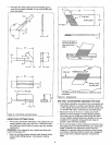
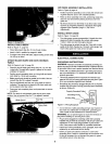
INSTALLING AND REMOVINGTHE RIVING KNIFE
Refer to Figure 13, page 26.
Install
° Line upthe rivingknife (KeyNo.51) in the properdirection
to the mountingbracket (KeyNo.47).
° Pushtherivingknifeall the way down into the mounting
bracket.Make sure thelockpin (KeyNo.48) is lockedin
the hole of the rivingknife. (The lockhole is on thebutton
side of the rivingknife).
• Ifit is notlockedproperly,hold the fastening knob (KeyNo.
54) andpull the lockpin offand makesure the lockpinis
properlylocatedat the hole ofriving knife.Whileraisingor
loweringthe knife,pin willsnap intheholeof the knifewhen
locatedat one ofthe threepositions.
° Tightenthefastening knob.
11