


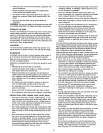
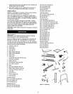
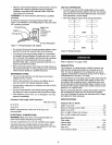
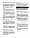
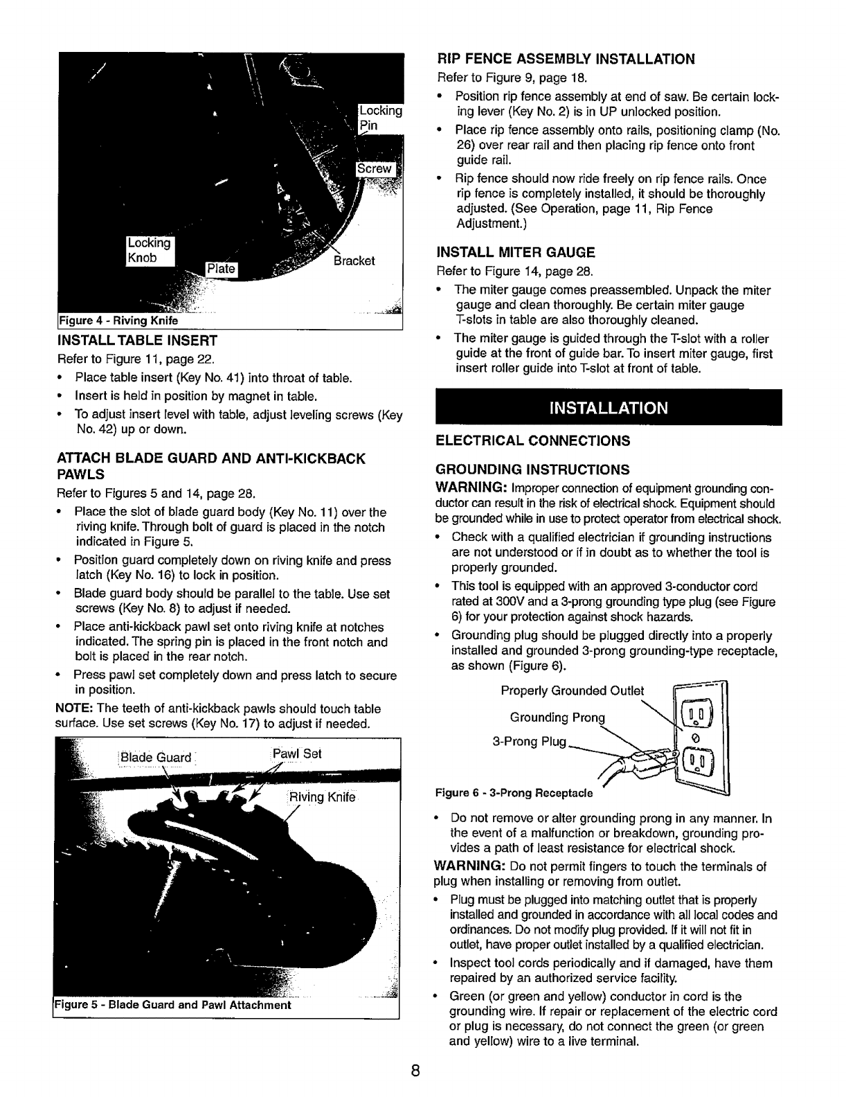
Locking
Pin
Figure 4 - Riving Knife
INSTALL TABLE INSERT
Referto Figure 11, page 22.
° Place table insert (Key No.41) into throat of table.
• Insert is held in position by magnet in table.
• Toadjust insert levelwith table, adjust leveling screws (Key
No. 42) up or down.
RIP FENCE ASSEMBLY INSTALLATION
Refer to Figure 9, page 18.
° Positionrip fence assembly at end of saw.Be certainlock-
ing lever(KeyNo.2) isin UP unlockedposition.
° Place rip fence assembly ontorails,positioningclamp(No.
26) overrear rail and thenplacingripfence ontofront
guide rail.
° Rip fence should now ride freely on rip fence rails. Once
rip fence is completely installed, it should be thoroughly
adjusted. (See Operation, page 11, Rip Fence
Adjustment.)
INSTALL MITER GAUGE
Referto Figure 14, page 28.
° The mitergauge comespreassembled.Unpackthe miter
gauge and cleanthoroughly.Be certainmitergauge
T-slotsin tableare alsothoroughlycleaned.
° The mitergaugeis guidedthroughthe T-slotwitha roller
guideat the frontofguidebar.To insertmiter gauge,first
insert rollerguideintoT-slotat front of table.
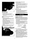
ATTACH BLADE GUARD AND ANTI-KICKBACK
PAWLS
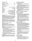
Refer to Figures 5 and 14, page 28.
• Placethe slot of blade guardbody (Key No. 11) overthe
riving knife.Throughbolt of guardis placed in the notch
indicatedin Figure5.
• Positionguardcompletelydownon rivingknifeand press
latch (KeyNo. 16) tolockin position.
° Bladeguardbody should be parallel tothe table.Use set
screws(Key No.8) to adjustif needed.
• Placeanti-kickbackpawlset ontorivingknifeat notches
indicated.The springpin isplacedin the front notchand
bolt is placed inthe rearnotch.
° Press pawlset completelydown and presslatchto secure
in position.
NOTE:The teeth of anti-kickback pawls should touchtable
surface. Use set screws (Key No. 17) to adjust if needed.
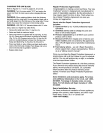
iBlade Guard Pawl Set
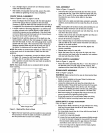
ELECTRICAL CONNECTIONS
GROUNDING INSTRUCTIONS
WARNING: improperconnectionof equipmentgroundingcon-
ductorcan resultinthe riskofelectricalshock.Equipmentshould
be groundedwhileinusetoprotectoperatorfrom electricalshock.
• Check witha qualifiedelectrician ifgroundinginstructions
are not understoodor if in doubtas to whetherthe tool is
properlygrounded.
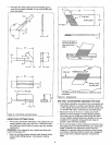
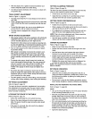
• Thistool isequippedwithan approved3-conductorcord
rated at 300V anda 3-pronggroundingtypeplug(see Figure
6) for yourprotectionagainst shock hazards.
• Grounding plug should be pluggeddirectlyintoa properly
installedand grounded3-prong grounding-typereceptacle,
as shown (Figure6).
Properly Grounded Outlet
Grounding Prong
3-Prong Plug ___
Figure 6 - 3-Prong Receptacle
° Do not remove or alter grounding prong in any manner. In
the event of a malfunction or breakdown, grounding pro-
vides a path of least resistance for electrical shock.
WARNING: Do not permit fingers to touch the terminals of
plug when installing or removing from outlet.
• Plug must be plugged into matching outlet that is properly
installed and grounded in accordance with all local codes and
ordinances. Do not modify plug provided. If it will not fit in
outlet, have proper outlet installed by a qualified electrician.
° Inspect tool cords periodically and if damaged, have them
repaired by an authorized service facility.
• Green (or green and yellow) conductor in cord is the
grounding wire. If repair or replacement of the electric cord
or plug is necessary, do not connect the green (or green
and yellow) wire to a live terminal.
8