


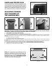
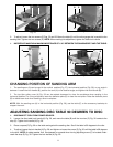
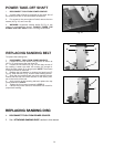

ADJUSTING BELT SANDER TABLE MITER GAUGE SLOT
PARALLEL TO SANDING BELT
1. DISCONNECT TOOL FROM POWER SOURCE.
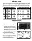
2. Position the table (Figs. 25 and 26) 90 degrees to the belt. Place a square (B) in the miter gauge slot with the
blade (C) of the square touching the sanding belt. Check the opposite end of the belt to see if the miter gauge slot (D)
is parallel to the belt.
10
ADJUSTING
SANDING BELT TABLE
90 DEGREES TO BELT
1. DISCONNECT TOOL FROM POWER SOURCE.
2. Loosen the table tilting lock handle (A) Fig. 21, move
the stop (B) into position, and rotate the table (C) until the
trunnion (D) contacts the stop (B). Tighten the lock handle (A).
NOTE: The lock handle (A) is spring-loaded and can be repo-
sitioned by pulling out the handle, moving it, and letting it
spring back into position.
3. Place a square (E) Fig. 21 on the table against the belt.
See if the table is 90 degrees to the belt.
4. To adjust, loosen the table tilting lock handle (A) Fig. 22.
Loosen the lock nut (F) Fig. 22, and turn the adjusting screw
(G) in or out until table is 90 degrees to the belt.
5. Tighten the lock nut (F) Fig. 22, and the lock handle (A)
Fig. 22.
6. The stop (G) Fig. 22 ensures that the belt table can
rapidly return to the 90 degree position after the table has
been tilted.
7. Adjust the pointer, if necessary, using the supplied
wrench.
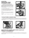
TILTING THE BELT SANDER TABLE
1. The table (A) can be tilted 45 degrees up (Fig. 23), or 45 degrees down (Fig. 24). To tilt the table, loosen the lock
handle (B), tilt the table to the desired angle, and tighten the lock handle (B). The degree of tilt is determined by the
pointer (C) and scale (D) Figs. 23 and 24. NOTE: When tilting the table down (Fig. 24), rotate the stop (E) Figs. 23 and
24 out of the way.
Fig. 21
Fig. 22
Fig. 23
Fig. 24
A
D
B
E
C
F
G
B
E
C
D
A
A
B
C
D
E
A