


11
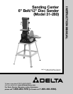
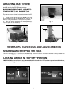
Fig. 28
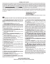
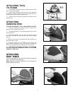
Fig. 27
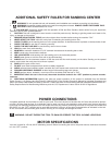
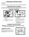
Fig. 26
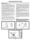
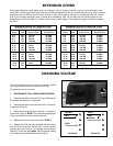
Fig. 25
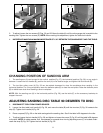
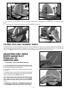
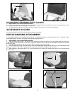
CHANGING POSITION OF SANDING ARM
1. The sanding arm (A) can be used in the vertical position (Fig. 27), the horizontal position (Fig. 28), or any angle in
between. Loosen the lock handle (B), position the arm (A) to the desired angle, and tighten the lock handle (B).
2. The top idler pulley cover (A) Fig. 28 can be rotated downward to clear the workpiece when sanding in the
horizontal position. For a long workpiece, lower the deflector plate (D) to clear the workpiece. Raise the deflector plate
(B) to deflect saw dust when sanding a short workpiece.
NOTE: With the sanding arm (A) in the horizontal position (Fig. 28), use the table (C) or the accessory backstop to
support the work.
A
B C
D E
A
B
C
D
E
A
B
A
D
C
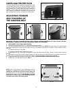
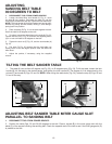
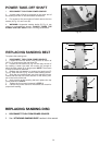
3. To adjust, loosen the two screws (E) Figs. 25 and 26. Move the table (A) until the miter gauge slot is parallel to the
sanding belt. Tighten the two screws (E). NOTE: When making this adjustment, tighten the table lock handle.
4. IMPORTANT: MAINTAIN A MAXIMUM DISTANCE OF 1/16" BETWEEN THE SANDING BELT AND THE TABLE.
ADJUSTING SANDING DISC TABLE 90 DEGREES TO DISC
1. DISCONNECT TOOL FROM POWER SOURCE.
2. Loosen the disc table lock handle (A) Fig. 29, and move the table (B) until the trunnion (C) Fig. 30 contacts the
stop (D). Tighten lock handle (A) Fig. 29.
3. Place a square (E) Fig. 30 on the table and against the sanding disc. See if the table is 90 degrees to the disc.
4. To adjust, loosen the lock handle (A) Fig. 29, and tighten or loosen the screw (F) Fig. 30 until the table is 90 degrees
to the disc. NOTE: A rubber washer that compresses or expands when turning adjusting screw (F) is located under-
neath the stop (D) Fig. 30. Tighten the lock handle (A) Fig. 29.
B