


2
5
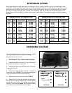
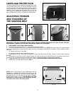
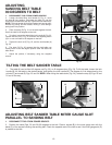
Use proper extension cords. Make sure your extension cord is in good condition and is a 3-wire extension cord
which has a 3-prong grounding type plug and matching receptacle which will accept the tool’s plug. When using an
extension cord, be sure to use one heavy enough to carry the current of the tool. An undersized cord will cause a
drop in line voltage, resulting in loss of power and overheating. Figs. 4A and 4B show the correct gauge to use
depending on the cord length. If in doubt, use the next heavier gauge. The smaller the gauge number, the heavier
the cord.
EXTENSION CORDS
Fig. 4A
MINIMUM GAUGE EXTENSION CORD
RECOMMENDED SIZES FOR USE WITH STATIONARY ELECTRIC TOOLS
Ampere Total Length Gauge of
Rating Volts of Cord in Feet Extension Cord
0-6 120
up to
25 18 AWG
0-6 120 25-50 16 AWG
0-6 120 50-100 16 AWG
0-6 120 100-150 14 AWG
6-10 120
up to
25 18 AWG
6-10 120 25-50 16 AWG
6-10 120 50-100 14 AWG
6-10 120 100-150 12 AWG
10-12 120
up to
25 16 AWG
10-12 120 25-50 16 AWG
10-12 120 50-100 14 AWG
10-12 120 100-150 12 AWG
12-16 120
up to
25 14 AWG
12-16 120 25-50 12 AWG
12-16 120
GREATER THAN 50 FEET NOT RECOMMENDED
MINIMUM GAUGE EXTENSION CORD
RECOMMENDED SIZES FOR USE WITH STATIONARY ELECTRIC TOOLS
Ampere Total Length Gauge of
Rating Volts of Cord in Feet Extension Cord
0-6 240
up to
50 18 AWG
0-6 240 50-100 16 AWG
0-6 240 100-200 16 AWG
0-6 240 200-300 14 AWG
6-10 240
up to
50 18 AWG
6-10 240 50-100 16 AWG
6-10 240 100-200 14 AWG
6-10 240 200-300 12 AWG
10-12 240
up to
50 16 AWG
10-12 240 50-100 16 AWG
10-12 240 100-200 14 AWG
10-12 240 200-300 12 AWG
12-16 240
up to
50 14 AWG
12-16 240 50-100 12 AWG
12-16 240
GREATER THAN 100 FEET NOT RECOMMENDED
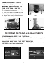
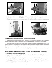
CHANGING VOLTAGE
The motor supplied with this tool is a dual voltage, 120/240
Volt, Single Phase motor and is wired for 120 volts.
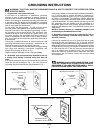
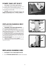
To operate the tool at 240 volts:
1. DISCONNECT TOOL FROM POWER SOURCE.
2. Remove the motor cover (A) Fig. 5 by loosening the
six screws that fasten it to the stand.
3. Remove the brown wire from terminal 2. Connect it
to terminal 6 (Fig. 6).
4. Remove the blue wire from terminal 4. Connect it
to terminal 2 (Fig. 6). NOTE: The wires have spade-type
quick connectors. No wire nuts are required.
5. Replace the motor cover removed in STEP 2.
6. Replace the 120 volt plug (supplied with the motor)
with a 240 volt plug that has two flat, current-carrying
prongs, and one round or “U” shaped ground prong.
(See Fig. 3) Use this plug ONLY with the proper mating
3-conductor grounded receptacle (See Fig. 3).
Fig. 5
Fig. 6
BROWN
RED
6
4
BLUE
1
120 VOLTS
240 VOLTS
2
BLUE
RED
6
4
BROWN
1
Fig. 4B
A